ZHCU759 July 2021
- 说明
- 资源
- 特性
- 应用
- 5
- 1System Description
-
2System Overview
- 2.1 Block Diagram
- 2.2
Design Considerations
- 2.2.1 System Control and Processing
- 2.2.2 Analog Front End
- 2.2.3 Input Voltage Monitoring: 5 V, 20 V, 40 V, and ±5 V
- 2.2.4 Bidirectional Current Sense: ±2 A
- 2.2.5 Unipolar Current Sense: 0.25 A to 1 A
- 2.2.6 TMP461-SP: Local and Remote Temperature Sensing
- 2.2.7 NTC Thermistor Temperature Sensing
- 2.2.8 Adjustable Voltage Source
- 2.2.9 Fixed Output Current Source
- 2.2.10 Adjustable 4-mA Current Source
- 2.2.11 Power Tree and Power Sequencing
- 2.3 Highlighted Products
- 3Hardware, Software, Testing Requirements, and Test Results
- 4Design and Documentation Support
- 5About the Author
3.3.5 Analog Outputs
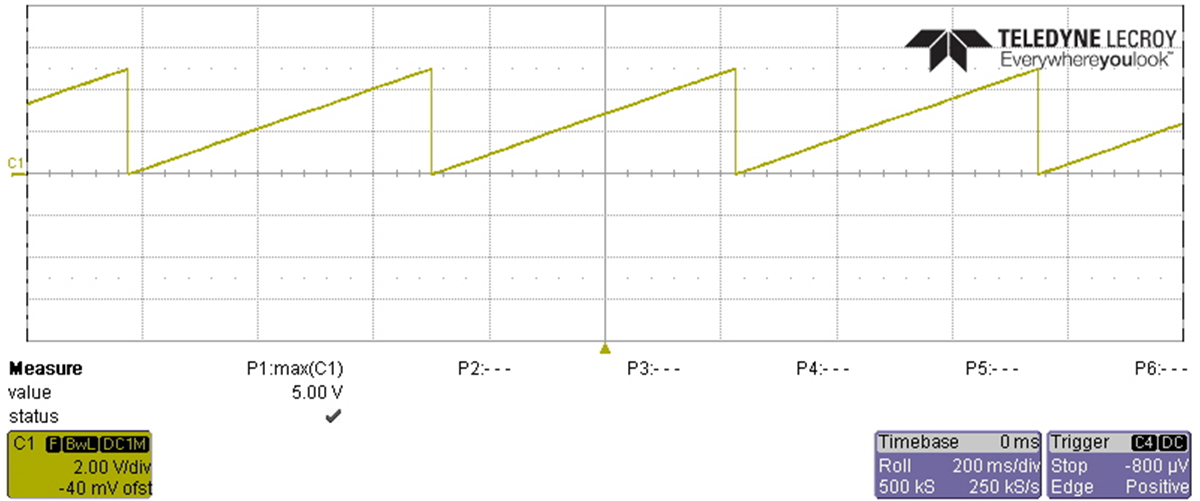
By default the software is setup to sweep the voltage from 0 to max resulting in the scope shot in Figure 3-16. The output of the DAC121S101QML-SP goes from 0–2.5 V, and the LMP7704-SP is setup to have a gain of 2 V/V which results in a 0- to 5-V output.
 Figure 3-16 Adjustable Voltage
Source
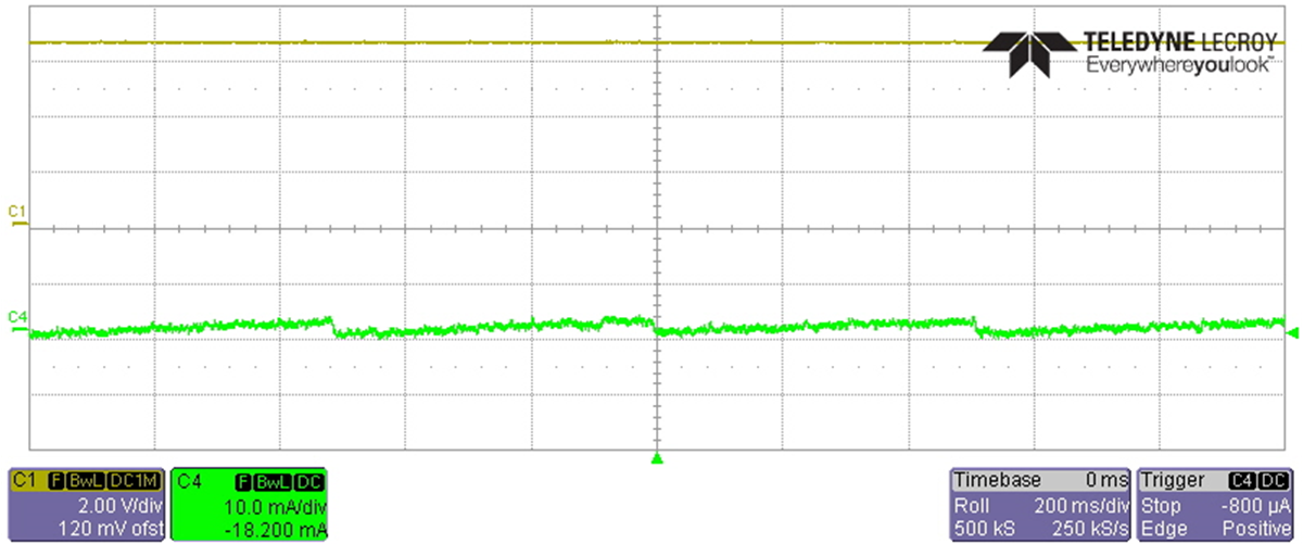
 Figure 3-17 Constant Current Output
Test Setup (7.5 V Applied)
 Figure 3-19 Constant Current Output
Test Setup (9 V Applied)
 Figure 3-18 Constant Current Output
Test Setup (8 V Applied)
 Figure 3-20 Adjustable 4-mA Current Source
6.5-V Input