ZHCU763 March 2021
- 说明
- 资源
- 特性
- 应用
- 5
- 1System Description
-
2System Overview
- 2.1 Block Diagram
- 2.2
Design Considerations
- 2.2.1 Multichannel SSR with Independent Isolation Between SSR Channels
- 2.2.2 Design Challenge With Single Isolation
- 2.2.3 Multichannel SSR Drive With Single Isolation Multichannel Digital Isolator
- 2.2.4 Need of High-Impedance Voltage Translator
- 2.2.5 Design to Minimize Cross-Coupling and MOSFET Gate Pick up Due to Other SSR Switching
- 2.2.6 Schematic: Design of Gate-Drive Circuit
- 2.2.7 Schematic: Digital Isolator Circuit
- 2.2.8 Schematic: 3.3 V to 10V_ISO, 5V_ISO Power Supply
- 2.3 Highlighted Products
- 3Hardware, Software, Testing Requirements, and Test Results
- 4Design and Documentation Support
- 5About the Author
3.3.4 Multichannel SSR Driven From Two 24-VAC Transformers
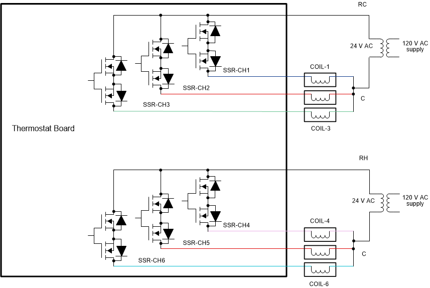
Figure 3-19 shows a 6-channel SSR topology powered from two transformers, for example from the cooling transformer (RC) and heating transformer (RH) in an HVAC thermostat. The common wires (C – wire) of both the transformers are connected together. The single-isolation gate-drive circuit in the reference design can be used to drive all the six SSR channels. However, in this case the turn on PNP transistor (Q1, Q2 in Figure 2-6) in the gate-drive circuit and the blocking diodes (D1, D2 in Figure 2-6) has to be rated for two times the peak AC voltage plus the gate-drive voltage (this is by considering a use case where the transformers are mis-wired to create opposite polarity). For example, with a 24-VAC ±20% AC supply, having a peak instantaneous value of 41 V, the gate-drive PNP transistors and the blocking diodes has to be rated for more than 100 V.
 Figure 3-19 Circuit Topology in Driving Multiple
SSRs With two AC Transformers