ZHCU763 March 2021
- 说明
- 资源
- 特性
- 应用
- 5
- 1System Description
-
2System Overview
- 2.1 Block Diagram
- 2.2
Design Considerations
- 2.2.1 Multichannel SSR with Independent Isolation Between SSR Channels
- 2.2.2 Design Challenge With Single Isolation
- 2.2.3 Multichannel SSR Drive With Single Isolation Multichannel Digital Isolator
- 2.2.4 Need of High-Impedance Voltage Translator
- 2.2.5 Design to Minimize Cross-Coupling and MOSFET Gate Pick up Due to Other SSR Switching
- 2.2.6 Schematic: Design of Gate-Drive Circuit
- 2.2.7 Schematic: Digital Isolator Circuit
- 2.2.8 Schematic: 3.3 V to 10V_ISO, 5V_ISO Power Supply
- 2.3 Highlighted Products
- 3Hardware, Software, Testing Requirements, and Test Results
- 4Design and Documentation Support
- 5About the Author
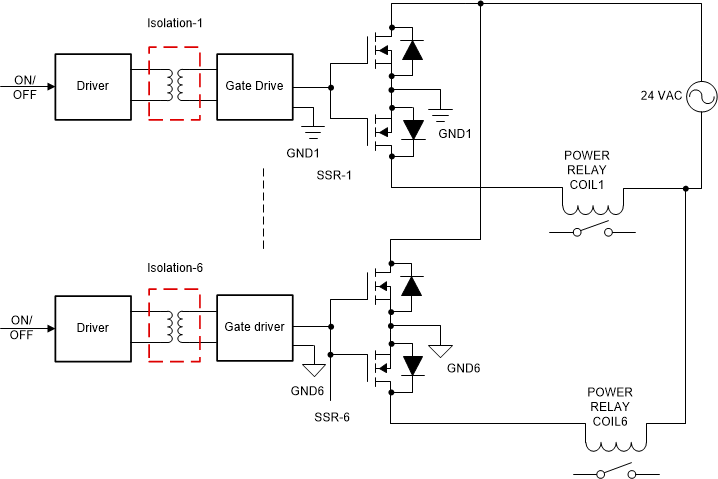
2.2.1 Multichannel SSR with Independent Isolation Between SSR Channels
Conventional SSR solutions use isolated gate
drive power supply for the MOSFETs of each SSR in a multichannel SSR circuit sharing the
same AC supply. For example, with a six-channel SSR circuit, the conventional solutions
use six isolation elements as shown in Figure 2-3, to eliminate potential turn on of relays, when other relays
connected in the same AC supply is turned on. The isolation can be realized using
independent transformers or optocouplers or capacitive isolators or any other isolation
methods. Use of individual isolated gate-drive circuits leads to increased system cost
and more board space.
 Figure 2-3 Multichannel SSR Topology With
Independent Isolation Between SSR Channels
 Figure 2-3 Multichannel SSR Topology With
Independent Isolation Between SSR Channels