ZHCU763 March 2021
- 说明
- 资源
- 特性
- 应用
- 5
- 1System Description
-
2System Overview
- 2.1 Block Diagram
- 2.2
Design Considerations
- 2.2.1 Multichannel SSR with Independent Isolation Between SSR Channels
- 2.2.2 Design Challenge With Single Isolation
- 2.2.3 Multichannel SSR Drive With Single Isolation Multichannel Digital Isolator
- 2.2.4 Need of High-Impedance Voltage Translator
- 2.2.5 Design to Minimize Cross-Coupling and MOSFET Gate Pick up Due to Other SSR Switching
- 2.2.6 Schematic: Design of Gate-Drive Circuit
- 2.2.7 Schematic: Digital Isolator Circuit
- 2.2.8 Schematic: 3.3 V to 10V_ISO, 5V_ISO Power Supply
- 2.3 Highlighted Products
- 3Hardware, Software, Testing Requirements, and Test Results
- 4Design and Documentation Support
- 5About the Author
2 System Overview
A solid-state relay (SSR) is an electronic switching device that switches on or off when a small external voltage is applied across its control terminals. SSRs consist of an input logic to respond to an appropriate input (control signal), a solid-state electronic switching device to switch power to the load circuitry, and a coupling mechanism to enable the control signal to activate this switch without mechanical parts. The SSR may be designed to switch either AC or DC to the load. The SSR serves the similar function as an electromechanical relay (EMR), but has no moving parts. SSRs use power semiconductor devices such as thyristors or transistors as power switches. SSRs have fast switching speeds compared with electromechanical relays and have no physical contacts to wear out. The life of an SSR is much longer compared to an EMR, as the life of EMR is limited by the switching cycle. The control signal must be coupled to the controlled circuit (SSR power switches) in a way that provides galvanic isolation between the two circuits.
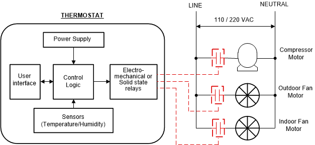
Thermostats are used as a user interface and controller in heating ventilation and air –conditioning (HVAC) systems. Thermostats use multiple relays to switch different loads like a heater, fan, compressor, valves, and so forth, as Figure 2-1 shows. The electromechanical relays used in thermostats are getting replaced by solid state relays (SSR) due to silent operation, increased life time, faster switching and so on. The number of relays used in a typical thermostat can vary from 3–12 depending upon HVAC system.
 Figure 2-1 Multiple Relays Controlling Different
Loads in Thermostats
Figure 2-1 Multiple Relays Controlling Different
Loads in ThermostatsConventional SSRs use functional isolation between each SSR channel to ensure reliable independent control between relays, which causes the solution to take more PCB space at a higher cost. This reference design uses single isolating elements for multiple SSRs, but still enables reliable and independent operation. The single isolation is provided between the microcontroller and the SSR power switches connected to 24 VAC power. The design uses a multichannel digital isolator with a single isolated power supply to control individual SSR channels. The design is rated for 24 VAC powered relays with current rating up to 2 A; however, this is easily scalable up to 240 VAC and a higher current rating. Each SSR channel consumes less than 75-mm2 space with the maximum height of the component within around 3 mm, enabling considerable size-savings compared to electromechanical relays. The low-cost open loop flyback to generate the single isolated power supply enables low board space and height. The design is tested for functional operation with 24 VAC power supply, illustrating independent control of each SSR channel without cross-coupling.