-
ADS869x 支持双极输入范围的 18 位 500kSPS 4 和 8 通道、单电源 SAR ADC
- 1 特性
- 2 应用
- 3 说明
- 4 修订历史记录
- 5 Device Comparison Table
- 6 Pin Configuration and Functions
- 7 Specifications
-
8 Detailed Description
- 8.1 Overview
- 8.2 Functional Block Diagram
- 8.3
Feature Description
- 8.3.1 Analog Inputs
- 8.3.2 Analog Input Impedance
- 8.3.3 Input Overvoltage Protection Circuit
- 8.3.4 Programmable Gain Amplifier (PGA)
- 8.3.5 Second-Order, Low-Pass Filter (LPF)
- 8.3.6 ADC Driver
- 8.3.7 Multiplexer (MUX)
- 8.3.8 Reference
- 8.3.9 Auxiliary Channel
- 8.3.10 ADC Transfer Function
- 8.3.11 Alarm Feature
- 8.4
Device Functional Modes
- 8.4.1 Device Interface
- 8.4.2
Device Modes
- 8.4.2.1 Continued Operation in the Selected Mode (NO_OP)
- 8.4.2.2 Frame Abort Condition (FRAME_ABORT)
- 8.4.2.3 STANDBY Mode (STDBY)
- 8.4.2.4 Power-Down Mode (PWR_DN)
- 8.4.2.5 Auto Channel Enable with Reset (AUTO_RST)
- 8.4.2.6 Manual Channel n Select (MAN_Ch_n)
- 8.4.2.7 Channel Sequencing Modes
- 8.4.2.8 Reset Program Registers (RST)
- 8.5
Register Maps
- 8.5.1 Command Register Description
- 8.5.2
Program Register Description
- 8.5.2.1 Program Register Read/Write Operation
- 8.5.2.2 Program Register Map
- 8.5.2.3
Program Register Descriptions
- 8.5.2.3.1 Auto-Scan Sequencing Control Registers
- 8.5.2.3.2 Device Features Selection Control Register (address = 03h)
- 8.5.2.3.3 Range Select Registers (addresses 05h-0Ch)
- 8.5.2.3.4 Alarm Flag Registers (Read-Only)
- 8.5.2.3.5 Alarm Threshold Setting Registers
- 8.5.2.3.6 Command Read-Back Register (address = 3Fh)
- 9 Application and Implementation
- 10Power-Supply Recommendations
- 11Layout
- 12器件和文档支持
- 13机械、封装和可订购信息
- 重要声明
DATA SHEET
ADS869x 支持双极输入范围的 18 位 500kSPS 4 和 8 通道、单电源 SAR ADC
本资源的原文使用英文撰写。 为方便起见,TI 提供了译文;由于翻译过程中可能使用了自动化工具,TI 不保证译文的准确性。 为确认准确性,请务必访问 ti.com 参考最新的英文版本(控制文档)。
1 特性
- 具有集成模拟前端的 18 位模数转换器 (ADC)
- 具有自动和手动扫描功能的 4 通道、8 通道多路复用器
- 通道独立可编程输入:
- ±10.24V、±5.12V、±2.56V
- 10.24V、5.12V
- 5V 模拟电源:1.65V 到 5V I/O 电源
- 恒定的阻性输入阻抗:1MΩ
- 输入过压保护:高达 ±20V
- 低漂移的片上 4.096V 基准电压
- 出色的性能:
- 500kSPS 的总吞吐量
- 差分非线性 (DNL):±0.5 最低有效位 (LSB);最大积分非线性 (INL):±1.5 LSB
- 增益误差和偏移误差的漂移均较低
- 信噪比 (SNR):93.5dB;总谐波失真 (THD):–105dB
- 低功耗:65mW
- AUX 输入 → 直接连接到 ADC 输入
- ALARM → 每通道的高低阈值
- SPI™- 兼容接口,支持菊花链连接
- 工业温度范围:-40°C 至 125°C
- TSSOP-38 封装 (9.7mm × 4.4mm)
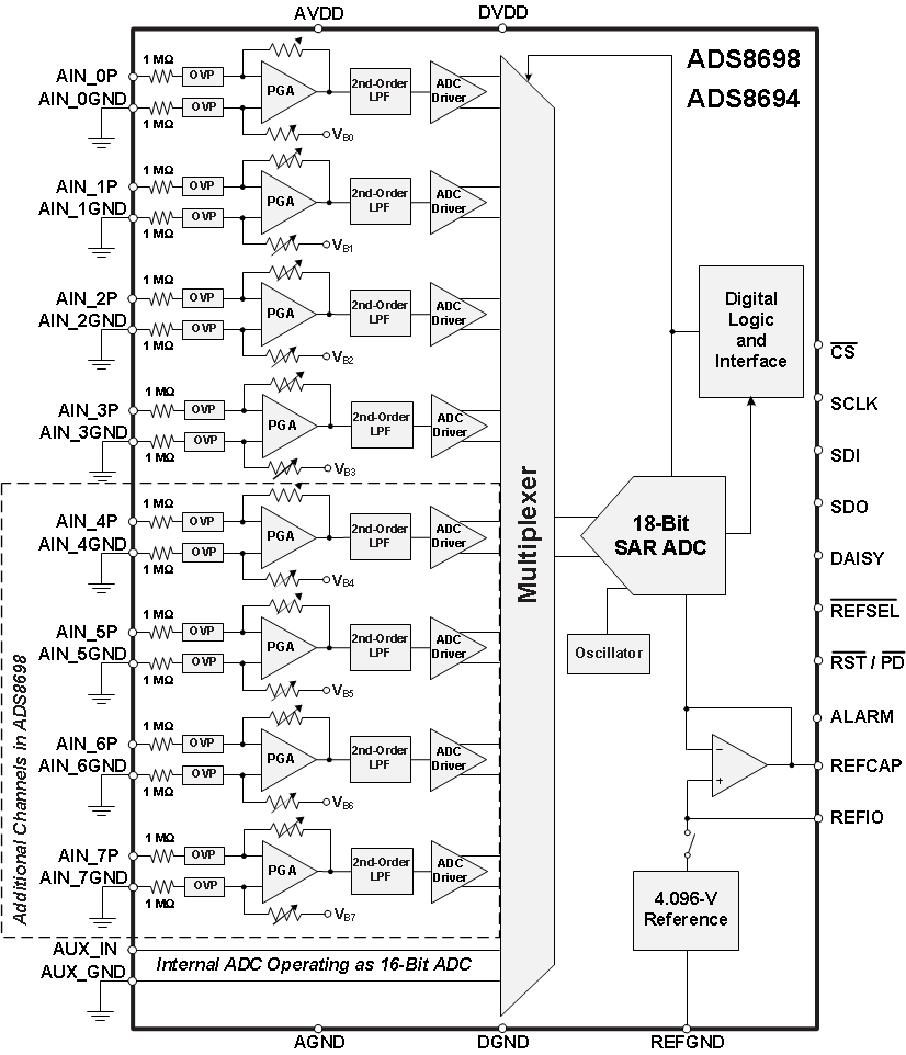
框图

2 应用
- 电力自动化
- 保护中继器
- PLC 模拟输入模块
3 说明
ADS8694 和 ADS8698 是基于 18 位逐次逼近寄存器 (SAR) 模数转换器 (ADC) 的 4 通道、8 通道集成数据采集系统,工作吞吐量达 500kSPS。 这些器件提供了用于各输入通道的集成模拟前端电路(过压保护高达 ±20V)、支持自动和手动两种扫描模式的 4 通道或 8 通道多路复用器、以及低温度漂移的片上 4.096V 基准电压。 这些器件由单个 5V 模拟电源供电,每个输入通道均可支持真正的双极输入范围(±10.24V、 ±5.12V 和 ±2.56V)和单极输入范围(0V 至 10.24V 以及 0V 至 5.12V)。 模拟前端在所有输入范围内的增益均经过了精确调整,以确保高直流精度。 输入范围的选择可通过软件进行编程,各通道输入范围的选择相互独立。 该器件提供了一个 1MΩ 的恒定阻性输入阻抗(无论所选输入范围为何)。
ADS8694 和 ADS8698 为数字主机提供了一个兼容串行外设接口 (SPI) 的简单串行接口,同时支持以菊花链方式连接多个器件。 数字电源可提供 1.65V 到 5.25V 范围内的电压,因此可直接连接各种主机控制器。
器件信息(1)
| 器件型号 | 封装 | 封装尺寸(标称值) |
|---|---|---|
| ADS869x | TSSOP (38) | 9.70mm x 4.40mm |
- 要了解所有可用封装,请见数据表末尾的可订购米6体育平台手机版_好二三四附录。
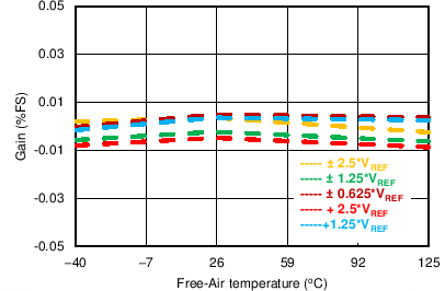
增益误差与温度的关系曲线

4 修订历史记录
| 日期 | 修订版本 | 注释 |
|---|---|---|
| 2014 年 7 月 | * | 首次发布。 |
5 Device Comparison Table
| PRODUCT | RESOLUTION (Bits) | CHANNELS | SAMPLE RATE (kSPS) |
|---|---|---|---|
| ADS8694 | 18 | 4, single-ended | 500 |
| ADS8698 | 18 | 8, single-ended | 500 |
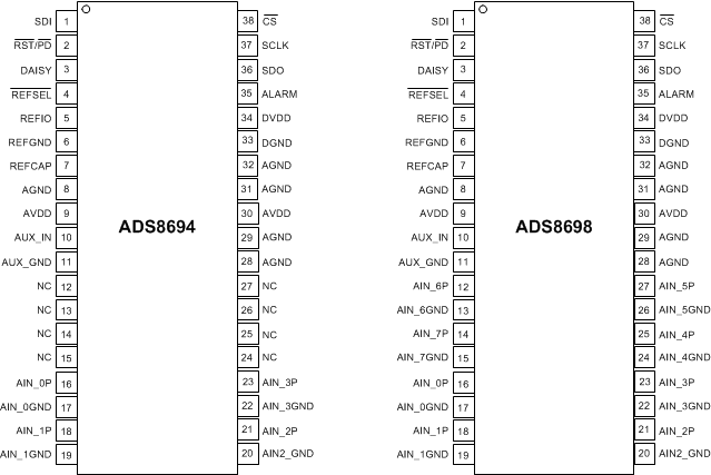
6 Pin Configuration and Functions
DBT Package
38-Pin TSSOP
Top View (Not to Scale)

Pin Functions
| PIN | I/O | DESCRIPTION | ||
|---|---|---|---|---|
| NO. | NAME | |||
| ADS8694 | ADS8698 | |||
| 1 | SDI | Digital input | Data input for serial communication. | |
| 2 | RST/PD | Digital input | Active low logic input. Dual functionality to reset or power-down the device. |
|
| 3 | DAISY | Digital input | Chain the data input during serial communication in daisy-chain mode. | |
| 4 | REFSEL | Digital input | Active low logic input to enable the internal reference. When low, the internal reference is enabled; REFIO becomes an output that includes the VREF voltage. When high, the internal reference is disabled; REFIO becomes an input to apply the external VREF voltage. |
|
| 5 | REFIO | Analog input, output | Internal reference output and external reference input pin. Decouple with REFGND on pin 6. | |
| 6 | REFGND | Power supply | Reference GND pin; short to the analog GND plane. Decouple with REFIO on pin 5 and REFCAP on pin 7. |
|
| 7 | REFCAP | Analog output | ADC reference decoupling capacitor pin. Decouple with REFGND on pin 6. | |
| 8 | AGND | Power supply | Analog ground pin. Decouple with AVDD on pin 9. | |
| 9 | AVDD | Power supply | Analog supply pin. Decouple with AGND on pin 8. | |
| 10 | AUX_IN | Analog input | Auxiliary input channel: positive input. Decouple with AUX_GND on pin 11. | |
| 11 | AUX_GND | Analog input | Auxiliary input channel: negative input. Decouple with AUX_IN on pin 10. | |
| 12 | NC | AIN_6P | Analog input | Analog input channel 6, positive input. Decouple with AIN_6GND on pin 13. No connection for the ADS8694; this pin can be left floating or connected to AGND. |
| 13 | NC | AIN_6GND | Analog input | Analog input channel 6, negative input. Decouple with AIN_6P on pin 12. No connection for the ADS8694; this pin can be left floating or connected to AGND. |
| 14 | NC | AIN_7P | Analog input | Analog input channel 7, positive input. Decouple with AIN_7GND on pin 15. No connection for the ADS8694; this pin can be left floating or connected to AGND. |
| 15 | NC | AIN_7GND | Analog input | Analog input channel 7, negative input. Decouple with AIN_7P on pin 14. No connection for the ; this pin can be left floating or connected to AGND. |
| 16 | AIN_0P | Analog input | Analog input channel 0, positive input. Decouple with AIN_0GND on pin 17. | |
| 17 | AIN_0GND | Analog input | Analog input channel 0, negative input. Decouple with AIN_0P on pin 16. | |
| 18 | AIN_1P | Analog input | Analog input channel 1, positive input. Decouple with AIN_1GND on pin 19. | |
| 19 | AIN_1GND | Analog input | Analog input channel 1, negative input. Decouple with AIN_1P on pin 18. | |
| 20 | AIN2_GND | Analog input | Analog input channel 2, negative input. Decouple with AIN_2P on pin 21. | |
| 21 | AIN_2P | Analog input | Analog input channel 2, positive input. Decouple with AIN_2GND on pin 20. | |
| 22 | AIN_3GND | Analog input | Analog input channel 3, negative input. Decouple with AIN_3P on pin 23. | |
| 23 | AIN_3P | Analog input | Analog input channel 3, positive input. Decouple with AIN_3GND on pin 22. | |
| 24 | NC | AIN_4GND | Analog input | Analog input channel 4, negative input. Decouple with AIN_4P on pin 25. No connection for the ADS8694; this pin can be left floating or connected to AGND. |
| 25 | NC | AIN_4P | Analog input | Analog input channel 4, positive input. Decouple with AIN_4GND on pin 24. No connection for the ADS8694; this pin can be left floating or connected to AGND. |
| 26 | NC | AIN_5GND | Analog input | Analog input channel 5, negative input. Decouple with AIN_5P on pin 27. No connection for the ADS8694; this pin can be left floating or connected to AGND. |
| 27 | NC | AIN_5P | Analog input | Analog input channel 5, positive input. Decouple with AIN_5GND on pin 26. No connection for the ADS8694; this pin can be left floating or connected to AGND. |
| 28 | AGND | Power supply | Analog ground pin | |
| 29 | AGND | Power supply | Analog ground pin | |
| 30 | AVDD | Power supply | Analog supply pin. Decouple with AGND on pin 31. | |
| 31 | AGND | Power supply | Analog ground pin. Decouple with AVDD on pin 30. | |
| 32 | AGND | Power supply | Analog ground pin | |
| 33 | DGND | Power supply | Digital ground pin. Decouple with DVDD on pin 34. | |
| 34 | DVDD | Power supply | Digital supply pin. Decouple with DGND on pin 33. | |
| 35 | ALARM | Digital output | Active high alarm output | |
| 36 | SDO | Digital output | Data output for serial communication | |
| 37 | SCLK | Digital input | Clock input for serial communication | |
| 38 | CS | Digital input | Active low logic input; chip-select signal | |