ZHCSFN9G August   2008  – December 2015 INA219

PRODUCTION DATA.  

  1. 特性
  2. 应用范围
  3. 说明
  4. 修订历史记录
  5. Related Products
  6. Pin Configuration and Functions
  7. Specifications
    1. 7.1 Absolute Maximum Ratings
    2. 7.2 ESD Ratings
    3. 7.3 Recommended Operating Conditions
    4. 7.4 Thermal Information
    5. 7.5 Electrical Characteristics:
    6. 7.6 Bus Timing Diagram Definitions
    7. 7.7 Typical Characteristics
  8. Detailed Description
    1. 8.1 Overview
    2. 8.2 Functional Block Diagram
    3. 8.3 Feature Description
      1. 8.3.1 Basic ADC Functions
        1. 8.3.1.1 Power Measurement
        2. 8.3.1.2 PGA Function
        3. 8.3.1.3 Compatibility With TI Hot Swap Controllers
    4. 8.4 Device Functional Modes
      1. 8.4.1 Filtering and Input Considerations
    5. 8.5 Programming
      1. 8.5.1 Programming the Calibration Register
      2. 8.5.2 Programming the Power Measurement Engine
        1. 8.5.2.1 Calibration Register and Scaling
      3. 8.5.3 Simple Current Shunt Monitor Usage (No Programming Necessary)
      4. 8.5.4 Default Settings
      5. 8.5.5 Bus Overview
        1. 8.5.5.1 Serial Bus Address
        2. 8.5.5.2 Serial Interface
      6. 8.5.6 Writing to and Reading from the INA219
        1. 8.5.6.1 High-Speed I2C Mode
        2. 8.5.6.2 Power-Up Conditions
    6. 8.6 Register Maps
      1. 8.6.1 Register Information
      2. 8.6.2 Register Details
        1. 8.6.2.1 Configuration Register (address = 00h) [reset = 399Fh]
      3. 8.6.3 Data Output Registers
        1. 8.6.3.1 Shunt Voltage Register (address = 01h)
        2. 8.6.3.2 Bus Voltage Register (address = 02h)
        3. 8.6.3.3 Power Register (address = 03h) [reset = 00h]
        4. 8.6.3.4 Current Register (address = 04h) [reset = 00h]
      4. 8.6.4 Calibration Register
        1. 8.6.4.1 Calibration Register (address = 05h) [reset = 00h]
  9. Application and Implementation
    1. 9.1 Application Information
    2. 9.2 Typical Application
      1. 9.2.1 Design Requirements
      2. 9.2.2 Detailed Design Procedure
        1. 9.2.2.1 Register Results for the Example Circuit
  10. 10Power Supply Recommendations
  11. 11Layout
    1. 11.1 Layout Guidelines
    2. 11.2 Layout Example
  12. 12器件和文档支持
    1. 12.1 社区资源
    2. 12.2 商标
    3. 12.3 静电放电警告
    4. 12.4 Glossary
  13. 13机械、封装和可订购信息

封装选项

机械数据 (封装 | 引脚)
散热焊盘机械数据 (封装 | 引脚)
订购信息

特性

  • 感测的总线电压范围:0V 至 26V
  • 报告电流、电压、和功率
  • 16 个可编程地址
  • 高精度:整个温度范围内的精度为 0.5%(最大值)(INA219B)
  • 滤波选项
  • 校准寄存器
  • 小外形尺寸晶体管 (SOT) 23-8 和小外形尺寸集成电路 (SOIC)-8 封装

应用范围

  • 服务器
  • 电信设备
  • 笔记本电脑
  • 电源管理
  • 电池充电器
  • 焊接设备
  • 电源
  • 测试设备

说明

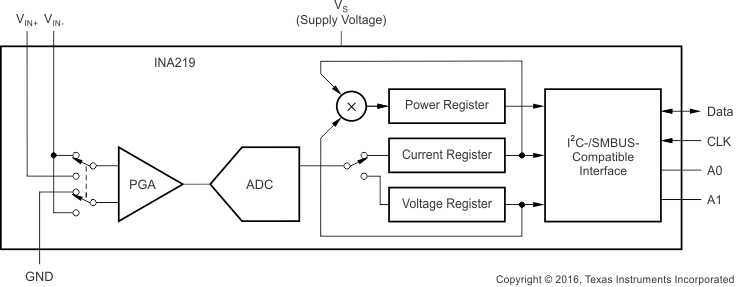
INA219 是一款具备 I2C 或 SMBUS 兼容接口的分流器和功率监测计。该器件监测分流器电压降和总线电源电压,转换次数和滤波选项可通过编程设定。可编程校准值与内部乘法器相结合,支持直接读取电流值(单位:安培)。通过附加乘法寄存器可计算功率(单位:瓦)。I2C 或 SMBUS 兼容接口 具有 16 个可编程地址。

INA219 提供两种级别:A 级和 B 级。B 级型号的精度更高且精密规范更加严格。

INA219 可在 0V 至 26V 范围内感测总线中的分压。该器件由 3V 至 5.5V 单电源供电,电源的最大流耗为 1mA。INA219 的工作温度范围为 -40°C 至 125°C。

器件信息(1)

器件型号 封装 封装尺寸(标称值)
INA219 SOIC (8) 3.91mm x 4.90mm
SOT-23 (8) 1.63mm x 2.90mm
  1. 要了解所有可用封装,请见数据表末尾的可订购米6体育平台手机版_好二三四附录。

简化电路原理图
INA219 frontpage_bos448.gif