SLLS933G November 2008 – January 2015 SN65HVD233-HT
PRODUCTION DATA.
- 1 Features
- 2 Applications
- 3 Description
- 4 Revision History
- 5 Description (Continued)
- 6 Pin Configuration and Functions
-
7 Specifications
- 7.1 Absolute Maximum Ratings
- 7.2 ESD Ratings
- 7.3 Recommended Operating Conditions
- 7.4 Thermal Information
- 7.5 Driver Electrical Characteristics
- 7.6 Receiver Electrical Characteristics
- 7.7 Driver Switching Characteristics
- 7.8 Receiver Switching Characteristics
- 7.9 Device Switching Characteristics
- 7.10 Typical Characteristics
- 8 Parameter Measurement Information
- 9 Detailed Description
- 10Application and Implementation
- 11Power Supply Recommendations
- 12Layout
- 13Device and Documentation Support
- 14Mechanical, Packaging, and Orderable Information
封装选项
机械数据 (封装 | 引脚)
散热焊盘机械数据 (封装 | 引脚)
订购信息
1 Features
- Bus-Pin Fault Protection Exceeds ±36 V
- Bus-Pin ESD Protection Exceeds 16-kV Human Body Model (HBM)
- Compatible With ISO 11898
- Signaling Rates(1) up to 1 Mbps
- Extended –7-V to 12-V Common-Mode Range
- High-Input Impedance Allows for 120 Nodes
- LVTTL I/Os Are 5-V Tolerant
- Adjustable Driver Transition Times for Improved Signal Quality
- Unpowered Node Does Not Disturb the Bus
- Low-Current Standby Mode: 200 µA Typical
- Power-Up and Power-Down Glitch-Free Bus Inputs and Outputs
- High-Input Impedance With Low VCC
- Monolithic Output During Power Cycling
- Loopback for Diagnostic Functions Available
- DeviceNet™ Vendor ID #806 (1)
2 Applications
- Down-Hole Drilling
- High-Temperature Environments
- Industrial Automation
- DeviceNet Data Buses
- Smart Distributed Systems (SDS™)
- SAE J1939 Data Bus Interfaces
- NMEA 2000 Data Bus Interfaces
- ISO 11783 Data Bus Interfaces
- CAN Data Bus Interfaces
- Controlled Baseline
- One Assembly or Test Site
- One Fabrication Site
- Available in Extreme (–55°C to 210°C) Temperature Range (1)
- Extended Product Life Cycle
- Extended Product-Change Notification
- Product Traceability
- Texas Instruments high-temperature products use highly optimized silicon (die) solutions with design and process enhancements to maximize performance over extended temperatures.
3 Description
The SN65HVD233 is used in applications employing the controller area network (CAN) serial communication physical layer in accordance with the ISO 11898 standard, with the exception that the thermal shutdown is removed. As a CAN transceiver, the device provides transmit and receive capability between the differential CAN bus and a CAN controller, with signaling rates up to 1 Mbps.
Designed for operation in especially harsh environments, the device features cross wire, overvoltage, and loss-of-ground protection to ±36 V, with common-mode transient protection of ±100 V. This device operates over a –7-V to 12-V common-mode range with a maximum of 60 nodes on a bus.
If the common-mode range is restricted to the ISO 11898 standard range of –2 V to 7 V, up to 120 nodes may be connected on a bus. This transceiver interfaces the single-ended CAN controller with the differential CAN bus found in industrial, building automation, and automotive applications.
Device Information(1)
| PART NUMBER | PACKAGE | BODY SIZE (NOM) |
|---|---|---|
| SN65HVD233-HT | SOIC (8) | 4.90 mm x 3.91 mm |
| CFP-HKJ (8) | 6.90 mm x 5.65 mm | |
| CFP-HKQ (8) | 6.90 mm x 5.65 mm | |
| CDIP SB (8) | 40.64 mm x 10.04 mm |
- For all available packages, see the orderable addendum at the end of the datasheet.
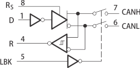
Functional Block Diagram

4 Revision History
Changes from F Revision (August 2012) to G Revision
- Added Handling Rating table, Feature Description section, Device Functional Modes, Application and Implementation section, Power Supply Recommendations section, Layout section, Device and Documentation Support section, and Mechanical, Packaging, and Orderable Information section Go