-
TLC591x 8-Channel Constant-Current LED Sink Drivers
- 1 Features
- 2 Applications
- 3 Description
- 4 Revision History
- 5 Device Comparison Table
- 6 Pin Configuration and Functions
-
7 Specifications
- 7.1 Absolute Maximum Ratings
- 7.2 ESD Ratings
- 7.3 Recommended Operating Conditions
- 7.4 Thermal Information
- 7.5 Electrical Characteristics: VDD = 3 V
- 7.6 Electrical Characteristics: VDD = 5.5 V
- 7.7 Switching Characteristics: VDD = 3 V
- 7.8 Switching Characteristics: VDD = 5.5 V
- 7.9 Timing Requirements
- 7.10 Typical Characteristics
- 8 Parameter Measurement Information
- 9 Detailed Description
- 10Application and Implementation
- 11Power Supply Recommendations
- 12Layout
- 13Device and Documentation Support
- 14Mechanical, Packaging, and Orderable Information
- IMPORTANT NOTICE
封装选项
机械数据 (封装 | 引脚)
散热焊盘机械数据 (封装 | 引脚)
订购信息
TLC591x 8-Channel Constant-Current LED Sink Drivers
1 Features
- Eight Constant-Current Output Channels
- Output Current Adjusted Through Single External Resistor
- Constant Output Current Range: 3-mA to 120-mA per Channel
- Constant Output Current Invariant to Load Voltage Change
- Open Load, Short Load and Overtemperature Detection
- 256-Step Programmable Global Current Gain
- Excellent Output Current Accuracy:
- Between Channels: < ±3% (Maximum)
- Between ICs: < ±6% (Maximum)
- Fast Response of Output Current
- 30-MHz Clock Frequency
- Schmitt-Trigger Input
- 3.3-V or 5-V Supply Voltage
- Maximum LED Voltage 20-V
- Thermal Shutdown for Overtemperature Protection
2 Applications
- General LED Lighting Applications
- LED Display Systems
- LED Signage
- Automotive LED Lighting
- White Goods
- Gaming Machines/Entertainment
3 Description
The TLC591x Constant-Current LED Sink Drivers are designed to work alone or cascaded. Since each output is independently controlled, they can be programmed to be on or off by the user. The high LED voltage (VLED) allows for the use of a single LED per output or multiple LEDs on a single string. With independently controlled outputs supplied with constant current, the LEDs can be combined in parallel to create higher currents on a single string. The constant sink current for all channels is set through a single external resistor. This allows different LED drivers in the same application to sink various currents which provides optional implementation of multi-color LEDs. An additional advantage of the independent outputs is the ability to leave unused channels floating. The flexibility of the TLC591x LED drivers is ideal for applications such as (but not limited to): 7-segment displays, scrolling single color displays, gaming machines, white goods, video billboards and video panels.
Device Information(1)
| PART NUMBER | PACKAGE | BODY SIZE (NOM) |
|---|---|---|
| TLC5916 | SOIC (16) | 9.90 mm × 3.91 mm |
| PDIP (16) | 19.30 mm × 6.35 mm | |
| TSSOP (16) | 5.00 mm × 4.40 mm | |
| TLC5917 | SOIC (16) | 9.90 mm × 3.91 mm |
| PDIP (16) | 19.30 mm × 6.35 mm | |
| TSSOP (16) | 5.00 mm × 4.40 mm |
- For all available packages, see the orderable addendum at the end of the datasheet.
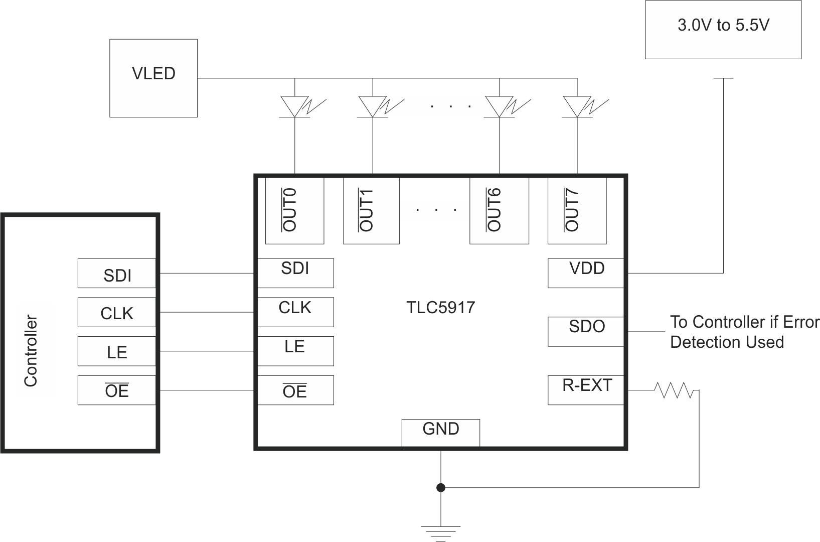
Single Implementation of TLC5916 / TLC5917 Device

4 Revision History
Changes from C Revision (February 2011) to D Revision
- Added Pin Configuration and Functions section, ESD Ratings table, Feature Description section, Device Functional Modes, Application and Implementation section, Power Supply Recommendations section, Layout section, Device and Documentation Support section, and Mechanical, Packaging, and Orderable Information section Go
Changes from B Revision (February 2011) to C Revision
- Replaced the Power Dissipation and Thermal Impedance table with the Thermal Information tablesGo
Changes from A Revision (November 2010) to B Revision
- Added Maximum LED Voltage 20-V to Features.Go
- Added Abstract section.Go
- Changed resistor value in Single Implementation diagram from 840Ω to 720Ω.Go
- Changed Default Relationship Curve to reflect correct data. Go
- Changed resistor value in Cascading Implementation diagram from 840Ω to 720Ω.Go
- Changed resistor value in Single Implementation diagram from 840Ω to 720Ω.Go
5 Device Comparison Table
| DEVICE(1) | OVERTEMPERATURE DETECTION | OPEN-LOAD DETECTION | SHORT TO GND DETECTION | SHORT TO VLED DETECTION |
|---|---|---|---|---|
| TLC5916 | X | X | X | — |
| TLC5917 | X | X | X | X |
6 Pin Configuration and Functions

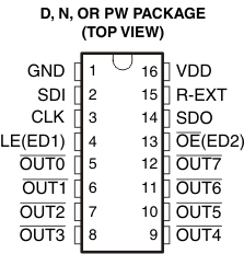
Pin Functions
| PIN | I/O | DESCRIPTION | |
|---|---|---|---|
| NAME | NO. | ||
| CLK | 3 | I | Clock input for data shift on rising edge |
| GND | 1 | – | Ground for control logic and current sink |
| LE(ED1) | 4 | I | Data strobe input Serial data is transferred to the respective latch when LE(ED1) is high. The data is latched when LE(ED1) goes low. Also, a control signal input for an Error Detection Mode and Current Adjust Mode (see Timing Diagram). LE(ED1) has an internal pulldown. |
| OE(ED2) | 13 | I | Output enable. When OE(ED2) is active (low), the output drivers are enabled; when OE(ED2) is high, all output drivers are turned OFF (blanked). Also, a control signal input for an Error Detection Mode and Current Adjust Mode (see Figure 11). OE(ED2) has an internal pullup. |
| OUT0 to OUT7 | 5 to 12 | O | Constant-current outputs |
| R-EXT | 15 | I | External Resistor - Connect an external resistor to ground to set the current for all outputs |
| SDI | 2 | I | Serial-data input to the Shift register |
| SDO | 14 | O | Serial-data output to the following SDI of next driver IC or to the microcontroller |
| VDD | 16 | I | Supply voltage |