SLIS135E December 2010 – February 2017
PRODUCTION DATA.
- 1 Features
- 2 Applications
- 3 Description
- 4 Revision History
- 5 Pin Configuration and Functions
- 6 Specifications
- 7 Detailed Description
- 8 Application and Implementation
- 9 Power Supply Recommendations
- 10Layout
- 11Device and Documentation Support
- 12Mechanical, Packaging, and Orderable Information
1 Features
- Two Potentiometers With 256-Position Resolution
- Non-Volatile Memory Stores Wiper Settings
- 10-kΩ End-to-End Resistance (TPL0202-10)
- Fast Power-Up Response Time: <100 µs
- ±1 LSB INL, ±0.5 LSB DNL (Voltage-Divider Mode)
- 12 ppm/°C Ratiometric Temperature Coefficient
- SPI Serial Interface
- 2.7 to 5.5 V Single-Supply Operation
- Operating Temperature Range From
–40°C to +105°C
2 Applications
- Adjustable Gain Amplifiers and Offset Trimming
- Adjustable Power Supplies
- Precision Calibration of Set Point Thresholds
- Sensor Trimming and Calibration
- Mechanical Potentiometer Replacement
3 Description
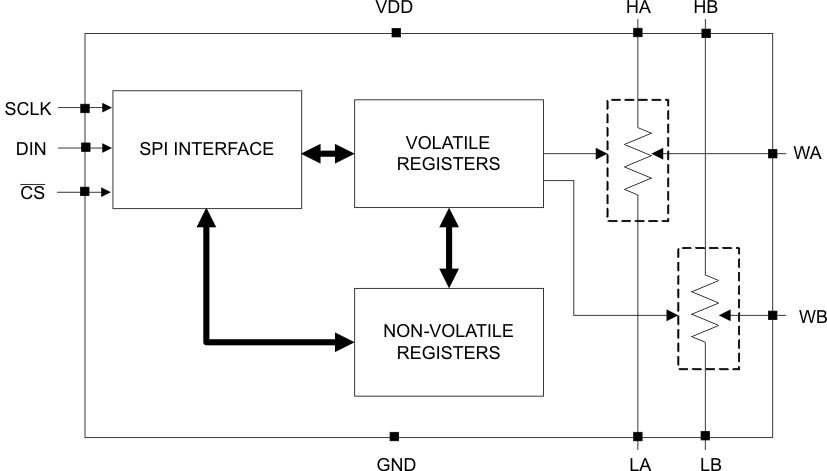
The TPL0202 has two linear-taper digital potentiometers (DPOTs) with 256 wiper positions. Each potentiometer can be used as a three-terminal potentiometer or as a two-terminal rheostat. The TPL0202-10 has an end-to-end resistance of 10 kΩ.
This DPOT can be used as a mechanical potentiometer replacement, allowing the user (or software) to digitally control and adjust resistance.
The TPL0202 has non-volatile memory (EEPROM) which can be used to store the wiper position for automatic recall upon power-up. The internal registers of the TPL0202 can be accessed using a SPI-compatible digital interface.
Device Information(1)
| PART NUMBER | PACKAGE | BODY SIZE (NOM) |
|---|---|---|
| TPL0202 | WQFN (16) | 3.00 mm × 3.00 mm |
- For all available packages, see the orderable addendum at the end of the data sheet.
Simplified Schematic
