-
TPS7A88 双路 1A 低噪声 (3.8 µVRMS)、LDO 稳压器
- 1 特性
- 2 应用
- 3 说明
- 4 修订历史记录
- 5 Pin Configuration and Functions
- 6 Specifications
-
7 Detailed Description
- 7.1 Overview
- 7.2 Functional Block Diagram
- 7.3 Feature Description
- 7.4 Device Functional Modes
- 8 Application and Implementation
- 9 Power Supply Recommendations
- 10Layout
- 11器件和文档支持
- 12机械、封装和可订购信息
- 重要声明
DATA SHEET
TPS7A88 双路 1A 低噪声 (3.8 µVRMS)、LDO 稳压器
本资源的原文使用英文撰写。 为方便起见,TI 提供了译文;由于翻译过程中可能使用了自动化工具,TI 不保证译文的准确性。 为确认准确性,请务必访问 ti.com 参考最新的英文版本(控制文档)。
1 特性
2 应用
- 高速模拟电路:
- 压控振荡器 (VCO)、模数转换器 (ADC)、数模转换器 (DAC) 以及低压差分信令 (LVDS)
- 成像:互补金属氧化物半导体 (CMOS) 传感器,视频专用集成电路 (ASIC)
- 测试和测量
- 仪器仪表、医疗和音频
- 数字负载:串化解串器 (SerDes),现场可编程栅极阵列 (FPGA), DSP™
3 说明
TPS7A88 是一款双路、低噪声 (3.8 µVRMS)、低压降 (LDO) 稳压器,每通道具有 1A 的拉电流能力,其最高压降仅为 200mV。
TPS7A88 提供两个独立的 LDO,极具灵活性,解决方案尺寸要比两个单通道 LDO 小 50% 左右。每个输出可通过外部电阻在 0.8V 至 5.0V 范围内进行调节。TPS7A88 的宽输入电压范围支持其在 1.4V 至 6.5V 范围内的电压下工作。
TPS7A88 的输出电压精度(整个线路、负载和温度范围内)达 1%,并且可通过软启动功能减少涌入电流,因此非常适合为敏感类模拟低压器件 [例如,压控振荡器 (VCO)、模数转换器 (ADC)、数模转换器 (DAC)、高端处理器和现场可编程门阵列 (FPGA)] 供电。
TPS7A88 旨在为噪声敏感类组件供电,广泛适用于高速通信、视频、医疗或测试和测量等 应用。此器件具有 4 µVRMS 的超低输出噪声和宽带电源抑制比 (PSRR) (1MHz 时为 40dB),最大限度减少了相位噪声和时钟抖动。这些 特性 最大限度提升了计时器件、ADC 和 DAC 的性能。
器件信息(1)
| 器件型号 | 封装 | 封装尺寸(标称值) |
|---|---|---|
| TPS7A88 | WQFN (20) | 4.00mm x 4.00mm |
- 如需了解所有可用封装,请见数据表末尾的可订购米6体育平台手机版_好二三四附录。
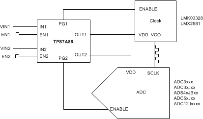
典型应用图

5 Pin Configuration and Functions
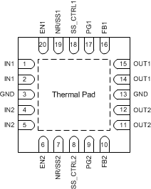
RTJ Package
4-mm × 4-mm 20-Pin WQFN
Top View

Pin Functions
| PIN | DESCRIPTION | ||
|---|---|---|---|
| NAME | NO. | I/O | |
| EN1 | 20 | I | Enable pin for each channel. These pins turn the regulator on and off. If VENx(1) ≥ VIH(ENx), the regulator is enabled. If VENx ≤ VIL(ENx), the regulator is disabled. The ENx pin must be connected to INx if the enable function is not used. |
| EN2 | 6 | ||
| FB1 | 16 | I | Feedback pin for each channel. These pins are the inputs to the control loop error amplifier and are used to set the output voltage of the device. |
| FB2 | 10 | ||
| GND | 3, 13 | — | Device GND. Connect both pins to the device thermal pad. |
| IN1 | 1, 2 | I | Input pin for LDO1. A 10 µF or greater input capacitor is required to assure robust operation. |
| IN2 | 4, 5 | Input pin for LDO2. A 10 µF or greater input capacitor is required to assure robust operation. | |
| NR/SS1 | 19 | — | Noise reduction pin for each channel. Connect these pins to an external capacitor to bypass the noise generated by the internal band-gap reference. The capacitor reduces the output RMS noise to very low levels and sets the output ramp rate to limit inrush current. |
| NR/SS2 | 7 | ||
| OUT1 | 14, 15 | O | Regulated output 1. A 10 µF or greater capacitor must be connected from this pin to GND to assure stability. |
| OUT2 | 11, 12 | Regulated output 2. A 10 µF or greater capacitor must be connected from this pin to GND to assure stability. | |
| PG1 | 17 | O | Open-drain power-good indicator pins for the LDO1 and LDO2 output voltages. A 10-kΩ to 100-kΩ external pullup resistor is required. These pins can be left floating or connected to GND if not used. |
| PG2 | 9 | ||
| SS_CTRL1 | 18 | I | Soft-start control pin for each channel. Connect these pins either to GND or INx to allow normal or fast charging of the NR/SSx capacitor. If a CNR/SSx capacitor is not used, SS_CTRLx must be connected to GND to avoid output overshoot. |
| SS_CTRL2 | 8 | ||
| Thermal pad | — | Connect the thermal pad to the printed circuit board (PCB) ground plane. | |
(1) Lowercase x indicates that the specification under consideration applies to both channel 1 and channel 2, one channel at a time.