ZHCSDI3A September 2014 – March 2015 UCC29950
PRODUCTION DATA.
- 1 特性
- 2 应用
- 3 说明
- 4 修订历史记录
- 5 Pin Configuration and Functions
- 6 Specifications
-
7 Detailed Description
- 7.1 Overview
- 7.2 Functional Block Diagram
- 7.3
Feature Description
- 7.3.1 Sense Networks
- 7.3.2 Sense Network Fault Detection
- 7.3.3 PFC Stage Soft-Start
- 7.3.4 AC Line Voltage Sensing
- 7.3.5 VBLK Sensing
- 7.3.6 AC Input UVLO and Brownout Protection
- 7.3.7 Dither
- 7.3.8 Active X-Cap Discharge
- 7.3.9 LLC Stage Soft Start
- 7.3.10 PFC Stage Current Sensing
- 7.3.11 Input Power Limit
- 7.3.12 PFC Stage Soft Start
- 7.3.13 Hybrid PFC Control Loop
- 7.3.14 PFC Stage Second Current Limit
- 7.3.15 PFC Inductor and Bulk Capacitor Recommendations
- 7.3.16 PFC Stage Over Voltage Protection
- 7.3.17 LLC Stage Control
- 7.3.18 Driver Output Stages and Characteristic
- 7.3.19 LLC Stage Dead Time Profile
- 7.3.20 LLC Stage Current Sensing
- 7.3.21 LLC Three Level Over-Current Protection
- 7.3.22 Over-Temperature Protection
- 7.3.23 Fault Timer and Control
- 7.4 Device Functional Modes
-
8 Application and Implementation
- 8.1 Application Information
- 8.2
Typical Application
- 8.2.1 Design Requirements
- 8.2.2
Detailed Design Procedure
- 8.2.2.1 LLC Stage
- 8.2.2.2 LLC Switching Frequency
- 8.2.2.3 LLC Transformer Turns Ratio
- 8.2.2.4 LLC Stage Equivalent Load Resistance
- 8.2.2.5 LLC Gain Range
- 8.2.2.6 Select LN and QE
- 8.2.2.7 LLC No-Load Gain
- 8.2.2.8 Parameters of the LLC Resonant Circuit
- 8.2.2.9 Verify the LLC Resonant Circuit Design
- 8.2.2.10 LLC Primary-Side Currents
- 8.2.2.11 LLC Secondary-Side Currents
- 8.2.2.12 LLC Transformer
- 8.2.2.13 LLC Resonant Inductor
- 8.2.2.14 Combining the LLC Resonant Inductor and Transformer
- 8.2.2.15 LLC Resonant Capacitor
- 8.2.2.16 LLC Stage with Split Resonant Capacitor
- 8.2.2.17 LLC Primary-Side MOSFETs
- 8.2.2.18 LLC Output Rectifier Diodes
- 8.2.2.19 LLC Stage Output Capacitors
- 8.2.2.20 LLC Stage Over-Current Protection, Current Sense Resistor
- 8.2.2.21 Detailed Design Procedure for the PFC stage
- 8.2.2.22 PFC Stage Output Current Calculation
- 8.2.2.23 Line Current Calculation
- 8.2.2.24 Bridge Rectifier
- 8.2.2.25 PFC Boost Inductor
- 8.2.2.26 PFC Input Capacitor
- 8.2.2.27 PFC Stage MOSFET
- 8.2.2.28 PFC Boost Diode
- 8.2.2.29 Bulk Capacitor
- 8.2.2.30 PFC Stage Current Sense Resistor
- 8.2.3 Application Curves
- 8.3 Do's and Don'ts
- 9 Power Supply Recommendations
- 10Layout
- 11器件和文档支持
- 12机械封装和可订购信息
1 特性
- 高效功率因数校正 (PFC) 和半桥谐振逻辑链路控制 (LLC) 组合控制器
- 连续导通模式 (CCM) 升压功率因数校正
- 支持自偏置或辅助(外部)偏置工作模式
- 完全内部补偿的 PFC 环路
- 3 步轻松设计 PFC 级
(设计电压反馈、电流反馈和功率级) - 100kHz 固定 PFC 频率,具有抖动特性,可确保符合 EMI 标准
- 真正的输入功率限制,独立于线路电压
- 固定 LLC 频率工作范围为 70kHz 至 350kHz
- 死区变化范围为 LLC 半桥功率级的整个负载范围,可扩展零电压开关 (ZVS) 范围
- 三级 LLC 过流保护
- Hiccup 工作模式,可提供连续过载和短路保护
- 低待机功耗,由高压启动金属氧化物半导体场效应晶体管 (MOSFET) 和 X-Cap 放电功能共同实现
- 内置软启动和转换器排序功能,可简化设计
- 交流线路欠压保护,具有故障指示器
- PFC 总线过压和欠压保护
- 过温保护
- 用于扩展功率级的外部栅极驱动器
- 小外形尺寸集成电路 (SOIC)-16 封装
2 应用
- 离线交流-直流服务器电源(通过 80 PLUS® 铜牌/银牌/金牌认证)
- 工业 DIN 导轨和开放式电源
- 游戏机和打印机电源
- 高密度适配器
- 照明驱动器
3 说明
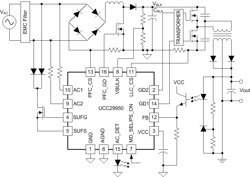
UCC29950 可为交流-直流转换器提供 LLC 转换器级和 CCM 升压功率因数校正 (PFC) 级,从而实现全部控制功能。 这款转换器经过了优化,非常便于使用。
凭借专有 CCM PFC 算法,系统能够获得高效率、更小的转换器尺寸以及高功率因数等诸多优势。 集成的 LLC 控制器可实现高效直流-直流转换级,利用软开关来降低电磁干扰 (EMI) 噪声。 这款组合控制器兼具 PFC 控制和 LLC 控制,使得控制算法能够充分利用来自两级的信息。
该控制器包含一个启动控制电路,此电路采用耗尽型 MOSFET 且内置器件电源管理功能,可最大程度降低外部元件需求,并且有助于降低系统实现成本。
为进一步降低待机功耗,该控制器还集成了 X-Cap 放电电路。 UCC29950 实现了一整套系统保护功能,其中包括交流线路欠压保护、PFC 总线欠压 PFC 和 LLC、过流保护和热关断保护。
器件信息(1)
| 器件型号 | 封装 | 封装尺寸(标称值) |
|---|---|---|
| UCC29950 | SOIC 16 引脚 (D) | 9.90mm x 6.00mm |
- 要了解所有可用封装,请见数据表末尾的可订购米6体育平台手机版_好二三四附录。
简化电路原理图

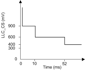
LLC 级过流保护曲线
