ZHCS267A May 2011 – December 2016
PRODUCTION DATA.
- 1 特性
- 2 应用
- 3 说明
- 4 修订历史记录
- 5 Pin Configuration and Functions
- 6 Specifications
-
7 Detailed Description
- 7.1 Overview
- 7.2 Functional Block Diagram
- 7.3
Feature Description
- 7.3.1
Analog-to-Digital Conversion (ADC)
- 7.3.1.1 General Features
- 7.3.1.2 3-to-6 Series Cell Configuration
- 7.3.1.3 Cell Voltage Measurements
- 7.3.1.4 GPAI or VBAT Measurements
- 7.3.1.5 Temperature Measurement
- 7.3.1.6 ADC Band-Gap Voltage Reference
- 7.3.1.7 Conversion Control
- 7.3.1.8 Secondary Protection
- 7.3.1.9 Cell Overvoltage Fault Detection (COV)
- 7.3.1.10 Cell Undervoltage Fault Detection (CUV)
- 7.3.1.11 Overtemperature Detection
- 7.3.1.12 Fault and Alert Behavior
- 7.3.1.13 Secondary Protector Built-In Self-Test Features
- 7.3.2 Cell Balancing
- 7.3.3 Other Features and Functions
- 7.3.4 Communications
- 7.3.1
Analog-to-Digital Conversion (ADC)
- 7.4 Device Functional Modes
- 7.5 Programming
- 7.6
Register Maps
- 7.6.1 I/O Register Details
- 7.6.2 Register Types
- 7.6.3
Register Details
- 7.6.3.1 DEVICE_STATUS Register (0x00)
- 7.6.3.2 GPAI (0x01, 0x02) Register
- 7.6.3.3 VCELLn Register (0x03…0x0e)
- 7.6.3.4 TEMPERATURE1 Register (0x0f, 0x10)
- 7.6.3.5 TEMPERATURE2 Register (0x11, 0x12)
- 7.6.3.6 ALERT_STATUS Register (0x20)
- 7.6.3.7 FAULT_STATUS Register (0x21)
- 7.6.3.8 COV_FAULT Register (0x22)
- 7.6.3.9 CUV_FAULT Register (0x23)
- 7.6.3.10 PARITY_H Register (0x24) [PRESULT_A (R/O)]
- 7.6.3.11 PARITY_H Register (0x25) [PRESULT_B (R/O)]
- 7.6.3.12 ADC_CONTROL Register (0x30)
- 7.6.3.13 IO_CONTROL Register (0x31)
- 7.6.3.14 CB_CTRL Register (0x32)
- 7.6.3.15 CB_TIME Register (0x33)
- 7.6.3.16 ADC_CONVERT Register (0x34)
- 7.6.3.17 SHDW_CTRL Register (0x3a)
- 7.6.3.18 ADDRESS_CONTROL Register (0x3b)
- 7.6.3.19 RESET Register (0x3c)
- 7.6.3.20 TEST_SELECT Register (0x3d)
- 7.6.3.21 E_EN Register (0x3f)
- 7.6.3.22 FUNCTION_CONFIG Register (0x40)
- 7.6.3.23 IO_CONFIG Register (0x41)
- 7.6.3.24 CONFIG_COV Register (0x42)
- 7.6.3.25 CONFIG_COVT Register (0x43)
- 7.6.3.26 CONFIG_UV Register (0x44)
- 7.6.3.27 CONFIG_CUVT Register (0x45)
- 7.6.3.28 CONFIG_OT Register (0x46)
- 7.6.3.29 CONFIG_OTT Register (0x47)
- 7.6.3.30 USERx Register (0x48-0x4b) (USER1-4)
- 8 Application and Implementation
- 9 Power Supply Recommendations
- 10Layout
- 11器件和文档支持
- 12机械、封装和可订购信息
1 特性
- 符合汽车应用 应用认证
- 具有符合 AEC-Q100 标准的下列结果:
- 器件温度 2 级:-40℃ 至 +105℃ 的环境运行温度范围
- 器件人体模型 (HBM) 分类等级 2
- 器件充电器件模型 (CDM) 分类等级 C4B
- 3 节至 6 节电池支持,所有化合物
- 热插拔
- 用于数据通信的高速串行外设接口 (SPI)
- 支持垂直堆叠的接口
- 器件之间无需隔离组件
- 高精度模数转换器 (ADC):
- ±1mV 典型精度
- 14 位分辨率,6µs 转换时间
- 九个 ADC 输入
- 支持同步测量的专用引脚
- 配置数据存储在具有差错校验/纠正 (ECC) 功能的一次性可编程 (OTP) 寄存器中
- 内置比较器(二级保护器)支持:
- 过压和欠压保护
- 过热保护
- 可编程的阈值和延迟时间
- 专用故障信号
- 支持安全超时功能的电芯均衡控制输出
- 通过外部组件设置均衡电流
- 电源电压范围:7.2V 至 27V 连续电压以及 36V 峰值
- 低功耗:
- 休眠电流典型值为 12µA,空闲电流典型值为 45µA
- 集成 5V、3mA 高精度 LDO
2 应用
- 电动车与混合动力电动车
- 不间断电源系统 (UPS)
- 电动自行车和电动踏板车
- 大型电池系统
3 说明
bq76PL536A-Q1 器件是用于三至六节串联锂离子电池的可堆叠电池监控器和保护器。bq76PL536A-Q1 集成了模拟前端 (AFE) 以及精密模数转换器 (ADC),用于精确测量电池电压。使用一个单独的 ADC 来测量温度。
除测量温度外,该器件还对各通道提供过压和欠压监控保护。通过非易失性存储器来存储用户可编程的保护阈值和延迟时间。一旦超出其中某个阈值,就会输出故障信号。
可通过堆叠式 bq76PL536A-Q1 器件来实现对由 192 节电池组成的电池组的支持。所有器件通过高速 SPI 接口进行连接。
器件信息(1)
| 器件型号 | 封装 | 封装尺寸(标称值) |
|---|---|---|
| bq76PL536A-Q1 | HTQFP (64) | 10.00mm x 10.00mm |
- 如需了解所有可用封装,请见数据表末尾的可订购米6体育平台手机版_好二三四附录。
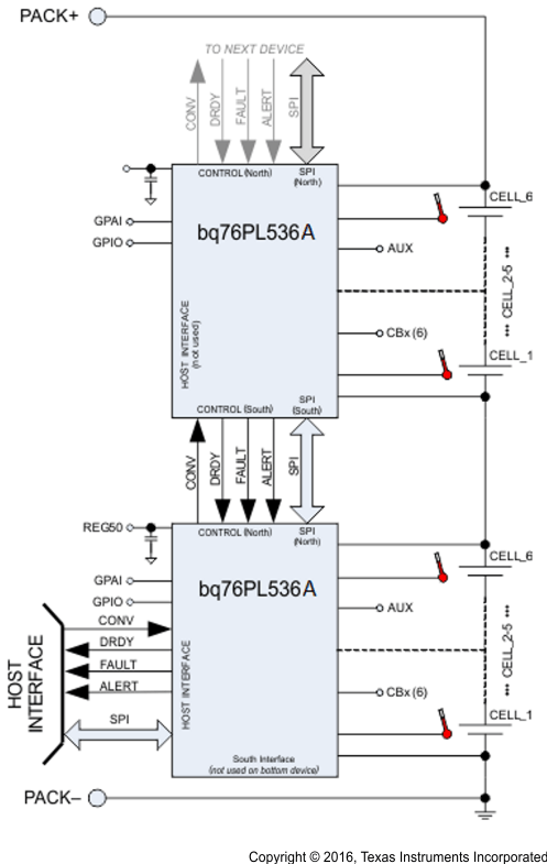
简化的系统连接

4 修订历史记录
Changes from * Revision (May 2011) to A Revision
- Added ESD 额定值表,特性 描述部分,器件功能模式,应用和实施部分,电源相关建议部分,布局部分,器件和文档支持部分以及机械、封装和可订购信息部分Go
- Changed 将电源电压范围从“6V 至 30V”更改为“7.2V 至 27V”(特性部分) Go
- Changed 描述 以使其更为简洁Go
- Changed graphic pin 54 alignment and part number Go
- Changed AUX description Go
- Listed values and removed VCn to VCn-1 row and updated Input Voltage Range and Output Voltage Range informationGo
- Changed "VBAT = 20 V" to "VBAT = 22 V" throughout data sheetGo
- Changed value to 27 VGo
- Combined Electrical Characteristics tables into one table Go
- Changed lower range to 7.2 Go
- Changed format of bottom two rows and added notes Go
- Deleted MAX value for VIHGo
- Deleted MIN value for VILGo
- Changed 120 to 125Go
- Changed test conditionGo
- Deleted note Go
- Added error range Go
- Changed table values and format Go
- Changed min valueGo
- Changed test conditions, Min and Nom values, and added note 4 Go
- Changed the section to be switching characteristics Go
- Changed units in equations to match unit in corresponding row Go
- Moved figure after timing requirements Go
- Changed name from VC0 to VSS Go
- Added TNOM table note Go
- Changed note wording for LDODxGo
- Changed warning to cautionGo
- Changed text to a warningGo
- Changed text to a caution and added SLEEP State in textGo
- Changed TS1(2) to TS1:TS2 throughout documentGo
- Changed SHADOW_LOAD to REFRESH Go
- Changed paragraph text and added cross-reference to section Go
- Changed definition of 1 value Go
- Changed text to Caution format.Go
- Changed anti-aliasing VCn input to VC6-VC1Go
- Changed "SN76PL536-Q1" to "bq76PL536A-Q1" in Power Supply DecouplingGo
- Changed note wording for LDODxGo