-
DACx300x 带自动检测型 I2C、PMBus™ 或 SPI 接口的 12 位和 10 位超低功率双路和单路电压和电流输出智能 DAC
- 1 特性
- 2 应用
- 3 说明
- 4 Revision History
- 5 Pin Configuration and Functions
-
6 Specifications
- 6.1 Absolute Maximum Ratings
- 6.2 ESD Ratings
- 6.3 Recommended Operating Conditions
- 6.4 Thermal Information
- 6.5 Electrical Characteristics: Voltage Output
- 6.6 Electrical Characteristics: Current Output
- 6.7 Electrical Characteristics: Comparator Mode
- 6.8 Electrical Characteristics: General
- 6.9 Timing Requirements: I2C Standard Mode
- 6.10 Timing Requirements: I2C Fast Mode
- 6.11 Timing Requirements: I2C Fast Mode Plus
- 6.12 Timing Requirements: SPI Write Operation
- 6.13 Timing Requirements: SPI Read and Daisy Chain Operation (FSDO = 0)
- 6.14 Timing Requirements: SPI Read and Daisy Chain Operation (FSDO = 1)
- 6.15 Timing Requirements: GPIO
- 6.16 Timing Diagrams
- 6.17 Typical Characteristics: Voltage Output
- 6.18 Typical Characteristics: Current Output
- 6.19 Typical Characteristics: Comparator
- 6.20 Typical Characteristics: General
-
7 Detailed Description
- 7.1 Overview
- 7.2 Functional Block Diagram
- 7.3 Feature Description
- 7.4 Device Functional Modes
- 7.5 Programming
- 7.6
Register Map
- 7.6.1 NOP Register (address = 00h) [reset = 0000h]
- 7.6.2 DAC-X-MARGIN-HIGH Register (address = 13h, 01h) [reset = 0000h]
- 7.6.3 DAC-X-MARGIN-LOW Register (address = 14h, 02h) [reset = 0000h]
- 7.6.4 DAC-X-VOUT-CMP-CONFIG Register (address = 15h, 03h) [reset = 0000h]
- 7.6.5 DAC-X-IOUT-MISC-CONFIG Register (address = 16h, 04h) [reset = 0000h]
- 7.6.6 DAC-X-CMP-MODE-CONFIG Register (address = 17h, 05h) [reset = 0000h]
- 7.6.7 DAC-X-FUNC-CONFIG Register (address = 18h, 06h) [reset = 0000h]
- 7.6.8 DAC-X-DATA Register (address = 1Ch, 19h) [reset = 0000h]
- 7.6.9 COMMON-CONFIG Register (address = 1Fh) [reset = 0FFFh]
- 7.6.10 COMMON-TRIGGER Register (address = 20h) [reset = 0000h]
- 7.6.11 COMMON-DAC-TRIG Register (address = 21h) [reset = 0000h]
- 7.6.12 GENERAL-STATUS Register (address = 22h) [reset = 00h, DEVICE-ID, VERSION-ID]
- 7.6.13 CMP-STATUS Register (address = 23h) [reset = 0000h]
- 7.6.14 GPIO-CONFIG Register (address = 24h) [reset = 0000h]
- 7.6.15 DEVICE-MODE-CONFIG Register (address = 25h) [reset = 0000h]
- 7.6.16 INTERFACE-CONFIG Register (address = 26h) [reset = 0000h]
- 7.6.17 SRAM-CONFIG Register (address = 2Bh) [reset = 0000h]
- 7.6.18 SRAM-DATA Register (address = 2Ch) [reset = 0000h]
- 7.6.19 BRDCAST-DATA Register (address = 50h) [reset = 0000h]
- 7.6.20 PMBUS-PAGE Register [reset = 0300h]
- 7.6.21 PMBUS-OP-CMD-X Register [reset = 0000h]
- 7.6.22 PMBUS-CML Register [reset = 0000h]
- 7.6.23 PMBUS-VERSION Register [reset = 2200h]
- 8 Application and Implementation
- 9 Power Supply Recommendations
- 10Layout
- 11Device and Documentation Support
- 12Mechanical, Packaging, and Orderable Information
- 重要声明
DATA SHEET
DACx300x 带自动检测型 I2C、PMBus™ 或 SPI 接口的 12 位和 10 位超低功率双路和单路电压和电流输出智能 DAC
本资源的原文使用英文撰写。 为方便起见,TI 提供了译文;由于翻译过程中可能使用了自动化工具,TI 不保证译文的准确性。 为确认准确性,请务必访问 ti.com 参考最新的英文版本(控制文档)。
1 特性
- 具有灵活配置的可编程电压或电流输出:
- 电压输出:
- 1LSB INL 和 DNL(10 位)
- 1x、1.5x、2x、3x 和 4x 增益
- 电流输出:
- 1LSB INL 和 DNL(8 位)
- 25μA 至 250μA 的单极和双极输出范围选项
- 电压输出:
- 电压输出模式具有 35μA/通道 IDD
- 适合所有通道的可编程比较器模式
- 当 VDD 关闭时提供高阻抗输出
- 高阻抗和电阻下拉断电模式
- 50MHz SPI 兼容型接口
- 自动检测的 I2C、PMBus™ 或 SPI 接口
- 1.62V VIH (VDD = 5.5V)
- 可配置为多种功能的通用输入/输出 (GPIO)
- 生成预定义的波形:正弦波、余弦波、三角形波、锯齿波
- 用户可编程的非易失性存储器 (NVM)
- 内部、外部或电源作为基准
- 宽工作电压范围:
- 电源:1.8V 至 5.5V
- 温度:-40˚C 至 +125˚C
- 微型封装:16 引脚 WQFN (3mm × 3mm)
3 说明
12 位 DAC63001 和 DAC63002 以及 10‑位 DAC53001 和 DAC53002(统称为 DACx300x)是一系列引脚兼容的超低功耗单通道和双通道缓冲电压输出和电流输出智能数模转换器 (DAC)。这些 DACx300x 器件支持高阻态断电模式,并在断电情况下支持高阻态输出。DAC 输出提供一个强制检测选项,可用作可编程比较器和电流阱。得益于多功能 GPIO、函数生成和 NVM,此类智能 DAC 可用于无处理器的 应用和设计复用。这些器件自动检测 I2C、PMBus 和 SPI 接口,并包含内部基准。
这些功能集与微型封装和超低功耗相结合,使这些智能 DAC 成为陆地移动无线电、脉搏血氧仪、笔记本电脑和其他电池供电应用的理想选择,以实现偏置、校准和波形生成。
器件信息
| 器件型号 | 封装(1) | 封装尺寸(标称值) |
|---|---|---|
| DACx3001 | WQFN (16) | 3.00mm x 3.00mm |
| DACx3002 |
(1) 如需了解所有可用封装,请参阅数据表末尾的可订购米6体育平台手机版_好二三四附录。
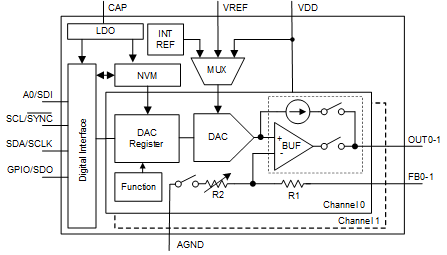
 简化版方框图