TIDT195 September 2020 – MONTH
Description
This non-isolated buck converter provides a fixed output of 12 V at 400 mA for BMS applications. It operates over an input voltage range of 50 VDC–150 VDC after a start-up greater than 40 V. Operating in Discontinuous Conduction Mode (DCM), this converter utilizes the UCC28730 controller, which is referenced to the switch node. It offers high efficiency and low cost in a compact form factor.
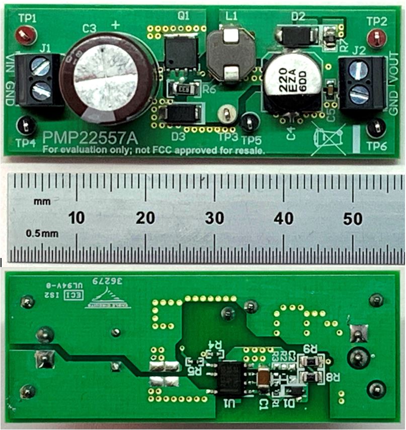
 Figure 1-1 Board Photos, Top and Bottom Views.