-
Why Monitoring Voltages Matters
Why Monitoring Voltages Matters
Aaron Paxton

Monitoring voltage rails is about as enthralling as doing yard work. And while most people don’t particularly enjoy pulling weeds or hedge trimming, it’s necessary to keep things from getting out of hand or having a significant other yell at you.
Fortunately, there are a myriad of ways to monitor your 1.8-V rails. Unfortunately, it’s not always clear which method is best. Part 1 of this blog series looks at why voltage monitoring is important.
Avoiding Brownout
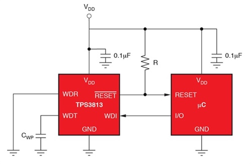
In the digital realm, brownout can cause processors to latch up and malfunction. For example, the minimum supply voltage in the MSP430™ microcontroller (MCU) line is 1.8V. Dropping the supply voltage below that threshold, even for a transient period, can mean trouble. Fortunately, many MSP430 MCUs incorporate their own reset IC to protect against this situation. If brownout occurs, the reset IC puts the processor into reset until the supply voltage rises to a tolerable level. If the voltage monitor is not already integrated into the MCU or if redundancy is required, it’s up to the engineer to implement it discretely, as shown in Figure 1.
 Figure 1 Voltage Supervisory and
Watchdog Monitoring with the TPS3813K33
Figure 1 Voltage Supervisory and
Watchdog Monitoring with the TPS3813K33Sensing Overvoltage Events
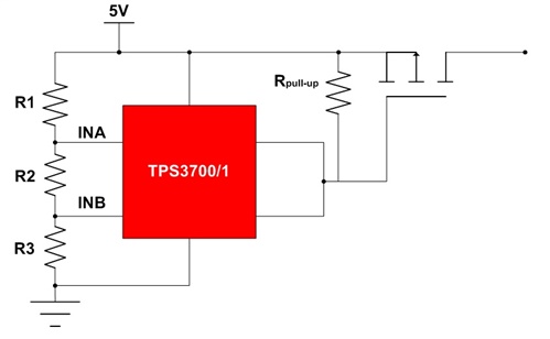
An IC’s absolute voltage rating is critical. Take the TPS61230 – the input-voltage range is rated to 5.5V during normal operation. The absolute maximum voltage applied at the input is 6V. Exceeding the absolute maximum voltage may cause reliability issues and/or permanent damage to the IC. Although the TPS61230 may be operating off a nominal 5V rail, inaccuracies or transient voltages may not be factored in. A 5V rail rated at 5% accuracy can easily be a 5.25V rail. With enough inductance on the line, loading the circuit can cause the voltage to spike, leading to a supply voltage above 6V. Preventive measures such as hot-swaps and e-fuses will help protect against these events. A reset IC may also be able to accomplish the same thing in some cases, as shown in Figure 2.
 Figure 2 Using a Window Comparator Such
as the TPS3700 Or TPS3701 To Sense a 5V Line for Overvoltage
Events
Figure 2 Using a Window Comparator Such
as the TPS3700 Or TPS3701 To Sense a 5V Line for Overvoltage
EventsBattery-level Monitoring
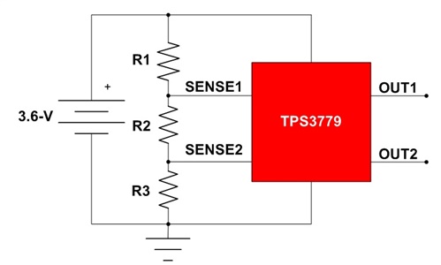
Making sure that lithium-ion (Li-ion) and other battery technologies do not stray from their safe operating areas is imperative. This includes preventing undercharge and overcharge states. While this is usually accomplished with battery management systems (BMS), voltage monitors can also protect the battery (or batteries) from such events. Figure 3 shows an implementation of using a dual voltage monitor to detect a drooping battery voltage.
 Figure 3 Monitoring a 3.6V Li-ion
Battery with the TPS3779
Figure 3 Monitoring a 3.6V Li-ion
Battery with the TPS3779Diagnostics
Aside from protection, a system may need to monitor its rails as part of an overall diagnostics strategy. An example is when a system is attempting to qualify for safety integrity level (SIL) recognition under the International Electrotechnical Commission (IEC) 61508 standard. Voltage monitors are a means of ensuring that your voltage rails are operating correctly.
Now that we’ve talked about why voltage monitoring is important, stay tuned for my next post on ways to implement voltage monitoring.
Additional Resources
- Review the supervisors overview on TI.com.
- Start simulating your design with the help of SPICE models for the TPS3779, TPS3700, TPS3701 and TPS61230.
IMPORTANT NOTICE AND DISCLAIMER
TI PROVIDES TECHNICAL AND RELIABILITY DATA (INCLUDING DATASHEETS), DESIGN RESOURCES (INCLUDING REFERENCE DESIGNS), APPLICATION OR OTHER DESIGN ADVICE, WEB TOOLS, SAFETY INFORMATION, AND OTHER RESOURCES “AS IS” AND WITH ALL FAULTS, AND DISCLAIMS ALL WARRANTIES, EXPRESS AND IMPLIED, INCLUDING WITHOUT LIMITATION ANY IMPLIED WARRANTIES OF MERCHANTABILITY, FITNESS FOR A PARTICULAR PURPOSE OR NON-INFRINGEMENT OF THIRD PARTY INTELLECTUAL PROPERTY RIGHTS.
These resources are intended for skilled developers designing with TI products. You are solely responsible for (1) selecting the appropriate TI products for your application, (2) designing, validating and testing your application, and (3) ensuring your application meets applicable standards, and any other safety, security, or other requirements. These resources are subject to change without notice. TI grants you permission to use these resources only for development of an application that uses the TI products described in the resource. Other reproduction and display of these resources is prohibited. No license is granted to any other TI intellectual property right or to any third party intellectual property right. TI disclaims responsibility for, and you will fully indemnify TI and its representatives against, any claims, damages, costs, losses, and liabilities arising out of your use of these resources.
TI’s products are provided subject to TI’s Terms of Sale (www.ti.com/legal/termsofsale.html) or other applicable terms available either on ti.com or provided in conjunction with such TI products. TI’s provision of these resources does not expand or otherwise alter TI’s applicable warranties or warranty disclaimers for TI products.
Mailing Address: Texas Instruments, Post Office Box 655303, Dallas, Texas 75265
Copyright © 2023, Texas Instruments Incorporated