ZHCSA60C May   2012  – May 2015 PCM5100A , PCM5100A-Q1 , PCM5101A , PCM5101A-Q1 , PCM5102A , PCM5102A-Q1

PRODUCTION DATA.  

  1. 特性
  2. 应用
  3. 说明
  4. 简化系统图
  5. 修订历史记录
  6. Device Comparison
  7. Pin Configuration and Functions
  8. Specifications
    1. 8.1 Absolute Maximum Ratings
    2. 8.2 ESD Ratings Updated ESD Data
    3. 8.3 Recommended Operating Conditions
    4. 8.4 Thermal Information
    5. 8.5 Electrical Characteristics
    6. 8.6 Timing Requirements
    7. 8.7 Timing Requirements, XSMT
    8. 8.8 Typical Characteristics
  9. Detailed Description
    1. 9.1 Overview
    2. 9.2 Functional Block Diagram
    3. 9.3 Feature Description
      1. 9.3.1 Terminology
      2. 9.3.2 Audio Data Interface
        1. 9.3.2.1 Audio Serial Interface
        2. 9.3.2.2 PCM Audio Data Formats
        3. 9.3.2.3 Zero Data Detect
      3. 9.3.3 XSMT Pin (Soft Mute / Soft Un-Mute)
      4. 9.3.4 Audio Processing
        1. 9.3.4.1 Interpolation Filter
      5. 9.3.5 Reset and System Clock Functions
        1. 9.3.5.1 Clocking Overview
        2. 9.3.5.2 Clock Slave Mode With Master/System Clock (SCK) Input (4 Wire I2S)
        3. 9.3.5.3 Clock Slave Mode with BCK PLL to Generate Internal Clocks (3-Wire PCM)
    4. 9.4 Device Functional Modes
      1. 9.4.1 External SCK and PLL Activation
        1. 9.4.1.1 Interpolation Filter Modes
        2. 9.4.1.2 44.1kHz De-emphasis
        3. 9.4.1.3 Audio Format
  10. 10Applications and Implementation
    1. 10.1 Application Information
      1. 10.1.1 Typical Applications
        1. 10.1.1.1 Example Design Requirements
        2. 10.1.1.2 Detailed Design Procedure
        3. 10.1.1.3 Application Curve
  11. 11Power Supply Recommendations
    1. 11.1 Power Supply Distribution and Requirements
    2. 11.2 Recommended Powerdown Sequence
      1. 11.2.1 Planned Shutdown
      2. 11.2.2 Unplanned Shutdown
    3. 11.3 External Power Sense Undervoltage Protection Mode
    4. 11.4 Power-On Reset Function
    5. 11.5 PCM510xA Power Modes
      1. 11.5.1 Setting Digital Power Supplies and I/O Voltage Rails
      2. 11.5.2 Power Save Modes
  12. 12Layout
    1. 12.1 Layout Guidelines
  13. 13器件和文档支持
    1. 13.1 相关链接
    2. 13.2 社区资源
    3. 13.3 商标
    4. 13.4 静电放电警告
  14. 14机械、封装和可订购信息
    1. 14.1 机械数据

封装选项

机械数据 (封装 | 引脚)
散热焊盘机械数据 (封装 | 引脚)
订购信息

1 特性

  • 超低带外噪声
  • 具有 BCK 基准的高性能集成音频锁相环 (PLL),可在内部生成 SCK
  • 直接线路电平 2.1 VRMS 输出
  • 无需隔直电容
  • 线路电平输出支持低至 1kΩ 的负载
  • 智能静音系统;软斜升或斜降搭配模拟静音,实现 120dB 静音信噪比 (SNR)
  • 接收 16、24 和 32 位音频数据
  • PCM 数据样式:I2S,左对齐
  • 当 LRCK 和 BCK 被置为无效时,自动进入省电模式
  • 1.8V 或3.3V 故障安全低压 CMOS (LVCMOS) 数字输入
  • 采用硬件引脚的简易配置
  • 单电源供电:14
    • 3.3V 模拟电源、1.8V 或3.3V 数字电源
  • 符合 AEC-Q100 标准

2 应用

  • A/V 接收器、DVD、BD 播放器
  • 汽车信息娱乐系统和远程信息处理
  • HDTV 接收器
  • 汽车售后加装放大器

3 说明

PCM510xA 器件属于单片 CMOS 集成电路系列,由立体声数模转换器 (DAC) 和采用薄型小外形尺寸 (TSSOP) 封装的附加支持电路组成。PCM510xA 器件使用 TI 最新一代高级分段 DAC 架构米6体育平台手机版_好二三四,可实现出色的动态性能并提升针对时钟抖动的耐受度。

凭借 DirectPath™电荷泵技术,PCM510xA 器件提供 2.1 VRMS 中央接地输出(设计人员无需在输出上连接隔直电容)以及传统意义上与单电源线路驱动器相关的外部静音电路。

集成线路驱动器的每个引脚支持低至 1kΩ 的负载,从而在性能上超过其他所有基于电荷泵的线路驱动器。

器件上集成的 PLL 免除了对于系统时钟(通常称为主时钟)的需要,从而实现一个 3 线制 I2C 连接并减少了系统电磁干扰 (EMI)。

智能时钟误差与 PowerSense 欠压保护采用双层系统,能够消除喀嗒和噼啪声。

相比许多传统的开关电容 DAC 架构,PCM510xA 系列能够将带外噪声控制在 20dB 的较低水平,从而减少下游放大器/ADC 中的 EMI 和混叠(在 100kHz(OBN 典型值)到 3MHz 之间测得)。

Table 1. 器件信息(1)

器件型号 封装 封装尺寸(标称值)
PCM5102A TSSOP (20) 5.50mm x 4.40mm
PCM5101A
PCM5100A
  1. 要了解所有可用封装,请见数据表末尾的可订购米6体育平台手机版_好二三四附录。
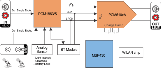
4 简化系统图

中的器件编号“PCM510x”至“PCM510xA”PCM5100A PCM5101A PCM5102A PCM5100A-Q1 PCM5101A-Q1 PCM5102A-Q1 pcm1865_pcm510x_sysdiag.gif