ZHCS234B August   2012  – January 2016 PCM5141 , PCM5142

PRODUCTION DATA.  

  1. 特性
  2. 应用
  3. 说明
  4. 修订历史记录
  5. Device Comparison
  6. Pin Configuration and Functions
    1. 6.1 Pin Functions
  7. Specifications
    1. 7.1  Absolute Maximum Ratings
    2. 7.2  ESD Ratings
    3. 7.3  Recommended Operating Conditions
    4. 7.4  Thermal Information
    5. 7.5  Electrical Characteristics
    6. 7.6  Timing Requirements: SCK Input
    7. 7.7  Timing Requirements: PCM Audio Data
    8. 7.8  Timing Requirements: I2S Master
    9. 7.9  Timing Requirements: XSMT
    10. 7.10 Switching Characteristics
    11. 7.11 Typical Characteristics
  8. Detailed Description
    1. 8.1 Overview
    2. 8.2 Functional Block Diagram
    3. 8.3 Feature Description
      1. 8.3.1 Terminology
      2. 8.3.2 Audio Data Interface
        1. 8.3.2.1 Audio Serial Interface
        2. 8.3.2.2 PCM Audio Data Formats
        3. 8.3.2.3 Zero Data Detect
      3. 8.3.3 XSMT Pin (Soft Mute / Soft Un-Mute)
      4. 8.3.4 Audio Processing
        1. 8.3.4.1 PCM514x Audio Processing Options
          1. 8.3.4.1.1 Overview
          2. 8.3.4.1.2 miniDSP Instruction Register
          3. 8.3.4.1.3 Digital Output
          4. 8.3.4.1.4 Software
        2. 8.3.4.2 Interpolation Filter
        3. 8.3.4.3 Fixed Audio Processing Flow (Program 5)
          1. 8.3.4.3.1 Processing Blocks - Detailed Descriptions
          2. 8.3.4.3.2 Biquad Section
          3. 8.3.4.3.3 Dynamic Range Compression
          4. 8.3.4.3.4 Stereo Mixer
          5. 8.3.4.3.5 Stereo Multiplexer
          6. 8.3.4.3.6 Mono Mixer
          7. 8.3.4.3.7 Master Volume Control
          8. 8.3.4.3.8 Miscellaneous Coefficients
      5. 8.3.5 DAC Outputs
        1. 8.3.5.1 Analog Outputs
        2. 8.3.5.2 Recommended Output Filter for the PCM514x
        3. 8.3.5.3 Choosing Between VREF and VCOM Modes
          1. 8.3.5.3.1 Voltage Reference and Output Levels
          2. 8.3.5.3.2 Mode Switching Sequence, from VREF Mode to VCOM Mode
        4. 8.3.5.4 Digital Volume Control
          1. 8.3.5.4.1 Emergency Ramp-Down
        5. 8.3.5.5 Analog Gain Control
      6. 8.3.6 Reset and System Clock Functions
        1. 8.3.6.1 Clocking Overview
        2. 8.3.6.2 Clock Slave Mode With Master and System Clock (SCK) Input (4 Wire I2S)
        3. 8.3.6.3 Clock Slave Mode With BCK PLL to Generate Internal Clocks (3-Wire PCM)
        4. 8.3.6.4 Clock Generation Using the PLL
        5. 8.3.6.5 PLL Calculation
          1. 8.3.6.5.1 Examples:
            1. 8.3.6.5.1.1 Recommended PLL Settings
        6. 8.3.6.6 Clock Master Mode from Audio Rate Master Clock
        7. 8.3.6.7 Clock Master from a Non-Audio Rate Master Clock
    4. 8.4 Device Functional Modes
      1. 8.4.1 Choosing a Control Mode
        1. 8.4.1.1 Software Control
          1. 8.4.1.1.1 SPI Interface
            1. 8.4.1.1.1.1 Register Read and Write Operation
          2. 8.4.1.1.2 I2C Interface
            1. 8.4.1.1.2.1 Slave Address
            2. 8.4.1.1.2.2 Register Address Auto-Increment Mode
            3. 8.4.1.1.2.3 Packet Protocol
            4. 8.4.1.1.2.4 Write Register
            5. 8.4.1.1.2.5 Read Register
            6. 8.4.1.1.2.6 Timing Characteristics
      2. 8.4.2 VREF and VCOM Modes
    5. 8.5 Programming
  9. Application and Implementation
    1. 9.1 Application Information
    2. 9.2 Typical Application
      1. 9.2.1 Design Requirements
      2. 9.2.2 Detailed Design Procedure
      3. 9.2.3 Application Curve
  10. 10Power Supply Recommendations
    1. 10.1 Power Supply Distribution and Requirements
    2. 10.2 Recommended Powerdown Sequence
      1. 10.2.1 XSMT = 0
      2. 10.2.2 Clock Error Detect
      3. 10.2.3 Planned Shutdown
      4. 10.2.4 Unplanned Shutdown
    3. 10.3 External Power Sense Undervoltage Protection Mode
    4. 10.4 Power-On Reset Function
      1. 10.4.1 Power-On Reset, DVDD 3.3-V Supply
      2. 10.4.2 Power-On Reset, DVDD 1.8-V Supply
    5. 10.5 PCM514x Power Modes
      1. 10.5.1 Setting Digital Power Supplies and I/O Voltage Rails
      2. 10.5.2 Power Save Modes
      3. 10.5.3 Power Save Parameter Programming
  11. 11Layout
    1. 11.1 Layout Guidelines
    2. 11.2 Layout Example
  12. 12Register Maps
    1. 12.1 PCM514x Register Map
      1. 12.1.1 Detailed Register Descriptions
        1. 12.1.1.1 Register Map Summary
        2. 12.1.1.2 Page 0 Registers
        3. 12.1.1.3 Page 1 Registers
        4. 12.1.1.4 Page 44 Registers
        5. 12.1.1.5 Page 253 Registers
      2. 12.1.2 PLL Tables for Software Controlled Devices
      3. 12.1.3 Coefficient Data Formats
      4. 12.1.4 Power Down and Reset Behavior
  13. 13器件和文档支持
    1. 13.1 开发支持
    2. 13.2 文档支持
    3. 13.3 相关链接
    4. 13.4 社区资源
    5. 13.5 商标
    6. 13.6 静电放电警告
    7. 13.7 Glossary
  14. 14机械、封装和可订购信息

封装选项

机械数据 (封装 | 引脚)
散热焊盘机械数据 (封装 | 引脚)
订购信息

1 特性

  • 可编程 miniDSP
  • 市场领先的低带外噪声特性
  • 可选数字滤波器延迟与性能
  • 无需隔离直流电流的电容器
  • 集成的负电荷泵
  • 智能静音系统;软斜升或斜降搭配模拟静音,实现 120dB 静音信噪比 (SNR)
  • 具有 BCK 基准的集成高性能音频锁相环 (PLL),可在内部生成 SCK
  • 接受 16 位、20 位、24 位和 32 位音频数据
  • 脉冲编码调制 (PCM) 数据格式:I2S、左对齐、右对齐、时分复用 (TDM)/数字信号处理 (DSP)
  • 通用串行接口 (SPI) 或者 I2C 控制
  • 软件或者硬件配置
  • 当 LRCK 和 BCK 被置为无效时,自动进入省电模式
  • 1.8V 或 3.3V 故障安全低电压互补金属氧化物半导体 (LVCMOS) 数字输入
  • 单电源供电运行:
    3.3V(模拟),1.8V 或 3.3V(数字)
  • 集成型加电复位
  • 小型28-pin TSSOP封装

2 应用

  • A/V 接收器
  • DVD,BD 播放器
  • HDTV 接收器
  • 需要 2 VRMS 音频输出的应用

3 说明

PCM514x 器件属于单片 CMOS 集成电路系列,由立体声数模转换器 (DAC) 和采用薄型小外形尺寸 (TSSOP) 封装的附加支持电路组成。PCM514x 使用 TI 最新一代高级分段 DAC 架构米6体育平台手机版_好二三四,可实现出色的动态性能并提升针对时钟抖动的耐受度。

PCM514x 系列器件集成了一个完全可编程的 miniDSP 内核,允许开发人员将滤波器、动态范围控件、定制插值器等各类 功能 集成到相关米6体育平台手机版_好二三四中。

PCM514x 提供 2.1 VRMS 中央接地输出(设计人员无需在输出上连接隔直电容)以及传统意义上与单电源线路驱动器相关的外部静音电路。

集成的线路驱动器支持低至 1kΩ 的负载,允许 PCM514x 驱动多达 10 个并联米6体育平台手机版_好二三四(例如 LCD TV、DVDR 和 AV 接收器),性能优于所有其他基于电荷泵的线路驱动器。

器件上集成的 PLL 免除了对于系统时钟(通常称为主时钟)的需要,从而实现一个 3 线制 I2C 连接并减少了系统电磁干扰 (EMI)。

器件信息

器件名称 封装 封装尺寸(标称值)
PCM5141 TSSOP (28) 9.70mm x 4.40mm
PCM5142

.

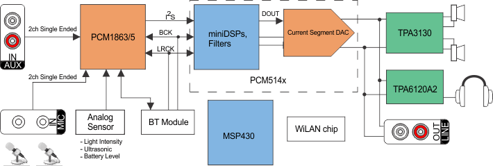
简化系统图

PCM5141 PCM5142 pcm1865_pcm514x_tpa3130_tpa6120a2_sysdiag.gif