ZHCSB67B April 2013 – April 2015 TAS5558
PRODUCTION DATA.
- 1 特性
- 2 应用
- 3 说明
- 4 修订历史记录
- 5 Pin Configuration and Functions
-
6 Specifications
- 6.1 Absolute Maximum Ratings
- 6.2 ESD Ratings
- 6.3 Recommended Operating Conditions
- 6.4 Thermal Information
- 6.5 Electrical Characteristics
- 6.6 Dynamic Performance
- 6.7 SRC Performance
- 6.8 Timing I2C Serial Control Port Operation
- 6.9 Reset Timing (RESET)
- 6.10 Power-Down (PDN) Timing
- 6.11 Back-End Error (BKND_ERR)
- 6.12 Mute Timing (MUTE)
- 6.13 Headphone Select (HP_SEL)
- 6.14 Switching Characteristics - Clock Signals
- 6.15 Switching Characteristics - Serial Audio Port
- 6.16 Volume Control
- 6.17 Typical Characteristics
-
7 Detailed Description
- 7.1 Overview
- 7.2 Functional Block Diagram
- 7.3 Feature Description
- 7.4
Device Functional Modes
- 7.4.1 Power Supply
- 7.4.2 Clock, PLL, and Serial Data Interface
- 7.4.3 Serial Audio Interface
- 7.4.4 I 2C Serial-Control Interface
- 7.4.5 Device Control
- 7.4.6 Energy Manager
- 7.4.7 Digital Audio Processor (DAP)
- 7.4.8 Pulse Width Modulation Schemes
- 7.4.9 TAS5558 DAP Architecture Diagrams
- 7.4.10 I 2C Coefficient Number Formats
- 7.4.11 Input Crossbar Mixer
- 7.4.12 Biquad Filters
- 7.4.13 Bass and Treble Controls
- 7.4.14 Volume, Automute, and Mute
- 7.4.15 Loudness Compensation
- 7.4.16 Dynamic Range Control (DRC)
- 7.4.17 THD Manager
- 7.4.18 Downmix Algorithm and I2S Out
- 7.4.19 Stereo Downmixes/(or Fold-Downs)
- 7.4.20 Output Mixer
- 7.4.21 Device Configuration Controls
- 7.4.22 Master Clock and Serial Data Rate Controls
- 7.4.23 Bank Controls (ASRC Bypass only)
- 7.5 Programming
- 7.6
Register Maps
- 7.6.1 Serial-Control I2C Register Summary
- 7.6.2
Serial-Control Interface Register Definitions
- 7.6.2.1 Clock Control Register (0x00)
- 7.6.2.2 General Status Register 0 (0x01)
- 7.6.2.3 Error Status Register (0x02)
- 7.6.2.4 System Control Register 1 (0x03)
- 7.6.2.5 System Control Register 2 (0x04)
- 7.6.2.6 Channel Configuration Control Registers (0x05-0x0C)
- 7.6.2.7 Headphone Configuration Control Register (0x0D)
- 7.6.2.8 Serial Data Interface Control Register (0x0E)
- 7.6.2.9 Soft Mute Register (0x0F)
- 7.6.2.10 Energy Manager Status Register (0x10)
- 7.6.2.11 Automute Control Register (0x14)
- 7.6.2.12 Output Automute PWM Threshold and Back-End Reset Period Register (0x15)
- 7.6.2.13 Modulation Index Limit Register (0x16, 0x17, 0x18, 0x19)
- 7.6.2.14 AD Mode - 8 Interchannel Channel Delay and Global Offset Registers (0x1B to 0x23)
- 7.6.2.15 Special Low Z and Mid Z Ramp/Stop Period (0x24)
- 7.6.2.16 PWM and EMO Control Register (0x25)
- 7.6.2.17 Individual Channel Shutdown (0x27)
- 7.6.2.18 Input Mux Registers (0x30, 0x31, 0x32, 0x33)
- 7.6.2.19 PWM Mux Registers (0x34, 0x35, 0x36, 0x37)
- 7.6.2.20 BD Mode and Ternary - 8 Interchannel Channel Delay (0x38 to 0x3F)
- 7.6.2.21 Bank-Switching Command Register (0x40) (TAS5558 + ASRC Bypass)
- 7.6.2.22 Input Mixer Registers, Channels 1-8 (0x41-0x48)
- 7.6.2.23 Bass Mixer Registers (0x49-0x50)
- 7.6.2.24 Biquad Filter Register (0x51-0x88)
- 7.6.2.25 Bass and Treble Register, Channels 1-8 (0x89-0x90)
- 7.6.2.26 Loudness Registers (0x91-0x95)
- 7.6.2.27 DRC1 Control Register CH1-7 (0x96) - Write
- 7.6.2.28 DRC2 Control Register CH8 (0x97) - Write Register
- 7.6.2.29 DRC1 Data Registers (0x98-0x9C)
- 7.6.2.30 DRC2 Data Registers (0x9D-0xA1)
- 7.6.2.31 DRC Bypass Registers (0xA2-0xA9)
- 7.6.2.32 Output Select and Mix Registers 8x2 (0x-0xAF)
- 7.6.2.33 8×3 Output Mixer Registers (0xB0-0xB1)
- 7.6.2.34 ASRC Registers (0xC3-C5)
- 7.6.2.35 Auto Mute Behavior (0xCC)
- 7.6.2.36 PSVC Volume Biquad Register (0xCF)
- 7.6.2.37 Volume, Treble, and Bass Slew Rates Register (0xD0)
- 7.6.2.38 Volume Registers (0xD1-0xD9)
- 7.6.2.39 Bass Filter Set Register (0xDA)
- 7.6.2.40 Bass Filter Index Register (0xDB)
- 7.6.2.41 Treble Filter Set Register (0xDC)
- 7.6.2.42 Treble Filter Index (0xDD)
- 7.6.2.43 AM Mode Register (0xDE)
- 7.6.2.44 PSVC Range Register (0xDF)
- 7.6.2.45 General Control Register (0xE0)
- 7.6.2.46 96kHz Dolby Downmix Coefficients (0xE3 to 0xE8)
- 7.6.2.47 THD Manager Configuration (0xE9 and 0xEA)
- 7.6.2.48 SDIN5 Input Mixer (0xEC-0xF3)
- 7.6.2.49 192kHZ Process Flow Output Mixer (0xF4-0xF7)
- 7.6.2.50 192kHz Dolby Downmix Coefficients (0xFB and 0xFC)
- 8 Application and Implementation
- 9 Power Supply Recommendations
- 10Layout
- 11器件和文档支持
- 12机械封装和可订购信息
1 特性
- 一般特性
- 8 通道异步采样率转换器
- 针对 32-192kHz(ARSC 至 96kHz)的 8 通道音频处理
- 频率为 192kHZ 的 4 通道本地音频处理
- 用于实现 DTS-HD 兼容性的 30kHz 音频带宽
- 用于总体系统功率控制的能量管理器
- 电源音量控制
- 音频输入或输出
- 多达 5 个同步串行音频输入(10 个通道)
- 多达 1 个同步串行音频输出(2 个通道)
- 针对时钟自动检测和跛行模式的已修整内部振荡器
- 具有自动/手工采样速率检测的受控模式 32-192kHz
- 8 个可支持 AD 或 BD 调制的差分 PWM 输出
- 两个差分 PWM 头戴式耳机输出
- 针对外部无线子
- PWM 输出的 I2S 支持单端 (S.E.) 或桥接负载 (BTL)
- 音频处理
- 音量控制范围为 18dB 至 -127dB(主控和八通道音量)
- 具有 ±18dB 范围、可选角频率的低音和高音音质控制
- 可配置响度补偿
- 两个具有两个阈值、两个偏移和三个斜坡的动态范围压缩器
- 每个通道七个二阶无限脉冲响应滤波器 (Biquad)
- 系数分组和自动组切换
- PWM 处理
- >105dB 的动态范围
- 总谐波失真 (THD)+N<0.1% (0-40kHz)
- 20Hz - 40kHz,针对 32KHz - 192KHz 的白噪声基准
- 具有可编程阈值和针对无噪声运行持续时间的灵活自动逻辑
- 高性能应用中的电源音量控制 (PSVC)
- 可调调制限制
2 应用
与大多数数字音频解码器的无缝对接
3 说明
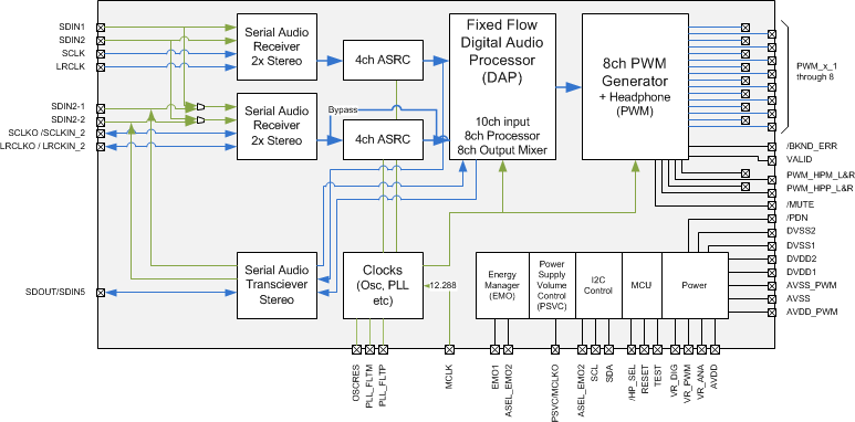
TAS5558 是一款具有数字音频处理功能和采样率转换器的 8 通道数字脉宽调制器 (PWM),具备先进的性能和较高的系统集成度。 TAS5558被设计用于支持 DTS-HD 规格蓝光 HTiB 应用。 ASRC 包含两个独立的模块,每个模块可处理 4 个通道。 因此,它能够支持多达两个不同的输入采样率。
米6体育平台手机版_好二三四 (TI) 功率级设计用于与 TAS5558 无缝配合工作。 TAS5558还提供一个高性能、差分输出以驱动一个外部、差分输入、模拟头戴式耳机放大器。
针对 48,96 和 192kHz 数据,TAS5558支持开关速率为 384kHz 的 AD,BD 和三重调制。 必须采用频率为 12.288MHz 的外部晶振。 TAS5558 还具备电源容量控制 (PSVC) 功能,可增大低功率级的动态范围,并且在与闭环 PWM 输入功率级一起使用时,可作为 G 类电源的一部分。
器件信息(1)
| 器件型号 | 封装 | 封装尺寸(标称值) |
|---|---|---|
| TAS5558 | HTSSOP (56) | 14.00mm x 6.10mm |
- 要了解所有可用封装,请见数据表末尾的可订购米6体育平台手机版_好二三四附录。
方框图
