ZHCSEX0A March 2016 – March 2016 TAS5733L
PRODUCTION DATA.
- 1 特性
- 2 应用
- 3 说明
- 4 修订历史记录
- 5 Pin Configuration and Functions
-
6 Specifications
- 6.1 Absolute Maximum Ratings
- 6.2 ESD Ratings
- 6.3 Recommended Operating Conditions
- 6.4 Thermal Characteristics
- 6.5 Electrical Characteristics
- 6.6 Speaker Amplifier Characteristics
- 6.7 Protection Characteristics
- 6.8 Master Clock Characteristics
- 6.9 I²C Interface Timing Requirements
- 6.10 Serial Audio Port Timing Requirements
- 6.11 Typical Characteristics - Stereo BTL Mode
- 6.12 Typical Characteristics - Mono PBTL Mode
-
7 Detailed Description
- 7.1 Overview
- 7.2 Functional Block Diagram
- 7.3 Audio Signal Processing Overview
- 7.4 Feature Description
- 7.5 Device Functional Modes
- 7.6 Programming
- 7.7
Register Maps
- 7.7.1 Register Summary
- 7.7.2
Detailed Register Descriptions
- 7.7.2.1 Clock Control Register (0x00)
- 7.7.2.2 Device ID Register (0x01)
- 7.7.2.3 Error Status Register (0x02)
- 7.7.2.4 System Control Register 1 (0x03)
- 7.7.2.5 Serial Data Interface Register (0x04)
- 7.7.2.6 System Control Register 2 (0x05)
- 7.7.2.7 Soft Mute Register (0x06)
- 7.7.2.8 Volume Registers (0x07, 0x08, 0x09)
- 7.7.2.9 Volume Configuration Register (0x0E)
- 7.7.2.10 Modulation Limit Register (0x10)
- 7.7.2.11 Interchannel Delay Registers (0x11, 0x12, 0x13, and 0x14)
- 7.7.2.12 PWM Shutdown Group Register (0x19)
- 7.7.2.13 Start/Stop Period Register (0x1A)
- 7.7.2.14 Oscillator Trim Register (0x1B)
- 7.7.2.15 BKND_ERR Register (0x1C)
- 7.7.2.16 Input Multiplexer Register (0x20)
- 7.7.2.17 PWM Output MUX Register (0x25)
- 7.7.2.18 AGL Control Register (0x46)
- 7.7.2.19 PWM Switching Rate Control Register (0x4F)
- 7.7.2.20 Bank Switch and EQ Control (0x50)
-
8 Application and Implementation
- 8.1 Application Information
- 8.2
Typical Applications
- 8.2.1
Stereo Bridge Tied Load Application
- 8.2.1.1 Design Requirements
- 8.2.1.2 Detailed Design Procedure
- 8.2.1.3 Application Performance Plots
- 8.2.2 Mono Parallel Bridge Tied Load Application
- 8.2.1
Stereo Bridge Tied Load Application
- 9 Power Supply Recommendations
- 10Layout
- 11器件和文档支持
- 12机械、封装和可订购信息
1 特性
- 音频输入/输出
- 单立体声串行音频输入
- 支持 44.1kHz 和 48kHz 采样速率 (LJ/RJ/I²S)
- 支持三线制 I²S 模式(无需 MCLK)
- 自动音频端口速率检测
- 支持桥接负载 (BTL) 和并行桥接负载 (PBTL) 配置
- POUT = 10 W(总谐波失真 + 噪声 (THD+N) 为 10% 时)
- PVDD = 12V、8Ω、1kHz
- 音频/脉宽调制 (PWM) 处理
- 独立通道音量控制,增益为静音到 24dB 增益(步长为 0.125dB)
- 可编程 3 波段自动增益限制 (AGL)
- 20 个可编程的 Biquad,适用于扬声器均衡 (EQ) 及其他音频处理 特性
- 总体说明 特性
- 104-dB 信噪比 (SNR),A 加权,以满量程 (0dB) 为基准
- 具有两个地址的 I²C 串行控制接口
- 热保护、短路保护和欠压保护
- 效率高达 90%
- AD、BD 和三重调制
- 脉宽调制 (PWM) 电平计量
2 应用
- LCD TV、LED TV
- 低成本音频设备
3 说明
TAS5733L 器件是一款高效数字输入音频放大器,用于驱动采用桥接负载 (BTL) 配置的立体声扬声器。对于并行桥接负载 (PBTL),该器件可将并行输出驱动为单个低阻抗负载,从而产生更高功率。一个串行数据输入可处理最多两个离散音频通道并能与大多数数字音频处理器和 MPEG 解码器无缝整合。此器件可接受宽范围的输入数据和数据传输速率。一个完全可编程数据路径将这些通道路由至内部扬声器驱动器。
TAS5733L 器件仅用作从器件,以接收外部提供的所有时钟。TAS5733L 器件采用开关频率介于 288kHz 和 384kHz 之间的 PWM 载波,具体取决于输入采样率。与四阶噪声整形器结合的过采样可提供一个白噪音基准以及 20Hz 至 20kHz 的出色动态范围。
器件信息(1)
| 器件型号 | 封装 | 封装尺寸(标称值) |
|---|---|---|
| TAS5733L | HTSSOP (48) | 12.50mm x 6.10mm |
- 要了解所有可用封装,请参见数据表末尾的可订购米6体育平台手机版_好二三四附录。
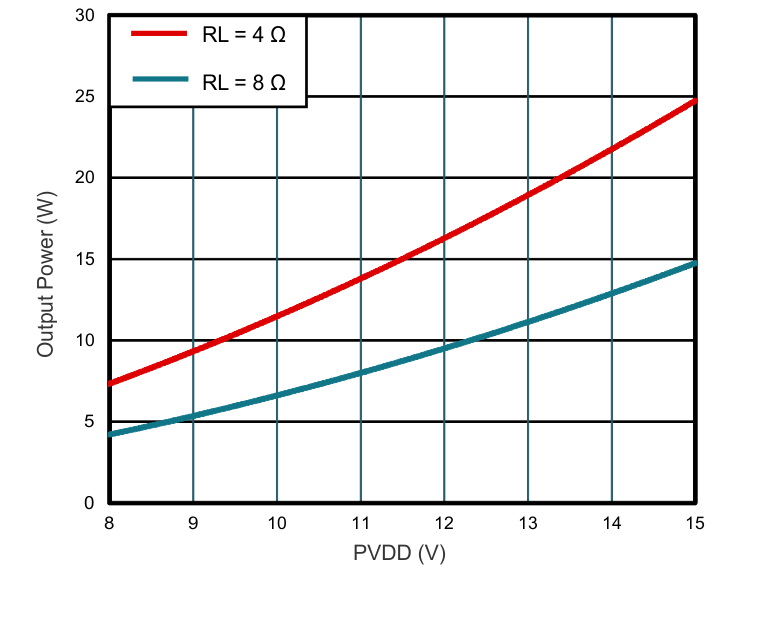
功率与 PVDD 间的关系

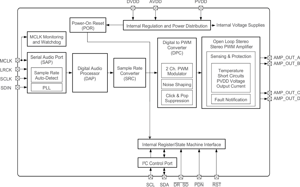
简化框图
