ZHCSCH4H June   2013  – November 2016 TPS65132

UNLESS OTHERWISE NOTED, this document contains PRODUCTION DATA.  

  1. 特性
  2. 应用范围
  3. 说明
  4. 修订历史记录
  5. Device Comparison Table
  6. Pin Configuration and Functions
  7. Specifications
    1. 7.1 Absolute Maximum Ratings
    2. 7.2 ESD Ratings
    3. 7.3 Recommended Operating Conditions
    4. 7.4 Thermal Information
    5. 7.5 Electrical Characteristics
    6. 7.6 I2C Interface Timing Requirements / Characteristics
    7. 7.7 Typical Characteristics
  8. Detailed Description
    1. 8.1 Overview
    2. 8.2 Functional Block Diagram
    3. 8.3 Feature Description
      1. 8.3.1 Undervoltage Lockout (UVLO)
      2. 8.3.2 Active Discharge
      3. 8.3.3 Boost Converter
        1. 8.3.3.1 Boost Converter Operation
        2. 8.3.3.2 Power-Up And Soft-Start (Boost Converter)
        3. 8.3.3.3 Power-Down (Boost Converter)
        4. 8.3.3.4 Isolation (Boost Converter)
        5. 8.3.3.5 Output Voltage (Boost Converter)
        6. 8.3.3.6 Advanced Power-Save Mode For Light-Load Efficiency And PFM
      4. 8.3.4 LDO Regulator
        1. 8.3.4.1 LDO Operation
        2. 8.3.4.2 Power-Up And Soft-Start (LDO)
        3. 8.3.4.3 Power-Down And Discharge (LDO)
        4. 8.3.4.4 Isolation (LDO)
        5. 8.3.4.5 Setting The Output Voltage (LDO)
      5. 8.3.5 Negative Charge Pump
        1. 8.3.5.1 Operation
        2. 8.3.5.2 Power-Up And Soft-Start (CPN)
        3. 8.3.5.3 Power-Down And Discharge (CPN)
        4. 8.3.5.4 Isolation (CPN)
        5. 8.3.5.5 Setting The Output Voltage (CPN)
    4. 8.4 Device Functional Modes
      1. 8.4.1 Enabling and Disabling the Device
    5. 8.5 Programming
      1. 8.5.1 I2C Serial Interface Description
      2. 8.5.2 I2C Interface Protocol
    6. 8.6 Register Maps
      1. 8.6.1 Registers
        1. 8.6.1.1 VPOS Register - Address: 0x00
        2. 8.6.1.2 VNEG Register - Address 0x01
        3. 8.6.1.3 DLYx Register - Address 0x02 (Only valid for TPS65132Sx)
        4. 8.6.1.4 APPS - SEQU - SEQD - DISP - DISN Register - Address 0x03
        5. 8.6.1.5 Control Register - Address 0xFF
      2. 8.6.2 Factory Default Register Value
  9. Application and Implementation
    1. 9.1 Application Information
    2. 9.2 Typical Applications
      1. 9.2.1 Low-current Applications (≤ 40 mA)
        1. 9.2.1.1 Design Requirements
        2. 9.2.1.2 Detailed Design Procedure
          1. 9.2.1.2.1 Sequencing
          2. 9.2.1.2.2 Boost Converter Design Procedure
            1. 9.2.1.2.2.1 Inductor Selection (Boost Converter)
            2. 9.2.1.2.2.2 Input Capacitor Selection (Boost Converter)
            3. 9.2.1.2.2.3 Output Capacitor Selection (Boost Converter)
          3. 9.2.1.2.3 Input Capacitor Selection (LDO)
          4. 9.2.1.2.4 Output Capacitor Selection (LDO)
          5. 9.2.1.2.5 Input Capacitor Selection (CPN)
          6. 9.2.1.2.6 Output Capacitor Selection (CPN)
          7. 9.2.1.2.7 Flying Capacitor Selection (CPN)
        3. 9.2.1.3 Application Curves
      2. 9.2.2 Mid-current Applications (≤ 80 mA)
        1. 9.2.2.1 Design Requirements
        2. 9.2.2.2 Detailed Design Procedure
          1. 9.2.2.2.1 Boost Converter Design Procedure
            1. 9.2.2.2.1.1 Inductor Selection (Boost Converter)
            2. 9.2.2.2.1.2 Input Capacitor Selection (Boost Converter)
            3. 9.2.2.2.1.3 Output Capacitor Selection (Boost Converter)
          2. 9.2.2.2.2 Input Capacitor Selection (LDO)
          3. 9.2.2.2.3 Output Capacitor Selection (LDO)
          4. 9.2.2.2.4 Input Capacitor Selection (CPN)
          5. 9.2.2.2.5 Output Capacitor Selection (CPN)
          6. 9.2.2.2.6 Flying Capacitor Selection (CPN)
        3. 9.2.2.3 Application Curves
      3. 9.2.3 High-current Applications (≤ 150 mA)
        1. 9.2.3.1 Design Requirements
        2. 9.2.3.2 Detailed Design Procedure
          1. 9.2.3.2.1 Sequencing
          2. 9.2.3.2.2 SYNC = HIGH
          3. 9.2.3.2.3 Startup
        3. 9.2.3.3 Application Curves
  10. 10Power Supply Recommendations
  11. 11Layout
    1. 11.1 Layout Guidelines
    2. 11.2 Layout Example
  12. 12器件和文档支持
    1. 12.1 器件支持
      1. 12.1.1 第三方米6体育平台手机版_好二三四免责声明
    2. 12.2 接收文档更新通知
    3. 12.3 社区资源
    4. 12.4 商标
    5. 12.5 静电放电警告
    6. 12.6 Glossary
  13. 13机械、封装和可订购信息
    1. 13.1 CSP 封装概要
      1. 13.1.1 芯片级封装尺寸
      2. 13.1.2 RVC 封装概要

封装选项

机械数据 (封装 | 引脚)
散热焊盘机械数据 (封装 | 引脚)
订购信息

特性

  • 输入电压范围:2.5V 至 5.5V
  • VPOS 升压转换器:
    由 4V 转换为 6V(步长为 0.1V)
  • VNEG 反相降压-升压转换器:
    由 -6V 转换为 -4V(步长为 0.1V)
  • 最大输出电流:
    80mA 或 150mA
  • 出色的综合效率
    • > 85%(IOUT > 10mA)
    • > 90%(IOUT > 40 mA)
  • 性能优异
    • 出色的瞬态响应
    • 在整个温度范围内保持 1% 的输出电压精度
  • I2C 接口
    • 可编程上电/掉电
      序列选项
    • 灵活的输出电压编程
    • 可编程有源输出放电
    • > 1000x 的可编程非易失性存储器
  • 欠压锁定和过热保护
  • 两种封装选项
    • 15 焊球芯片尺寸封装 (CSP)
    • 20 引脚四方扁平无引线 (QFN) 封装

应用范围

  • 小型、中型双极液晶显示屏 (LCD)
    • 智能手机、平板电脑
    • 摄像头、全球定位系统 (GPS)
    • 家庭自动化、销售点
    • 可穿戴设备(智能手表、活动追踪器)
  • 通用分离轨电源
    • 差分音频、耳机放大器
    • 仪表、运算放大器、比较器
    • 数模转换器/模数转换器 (DAC/ADC)

说明

TPS65132 系列设计用于支持正/负驱动 应用。该器件的两路输出均采用单电感方案,为用户提供尺寸最小的解决方案,在简化物料清单的同时保持高效。该器件可在低噪声条件下提供最佳线路和负载调节能力。凭借 2.5V 至 5.5V 的输入电压范围,该器件针对由单节电池(锂离子电池、锂镍电池和锂聚合物电池)供电的米6体育平台手机版_好二三四以及固定电压为 3.3V 和 5V 的电源轨进行了优化。TPS656132 系列器件提供 80mA 和 150mA 输出电流选项,可通过编程设定为 40mA。提供 CSP 和 QFN 两种封装选项。

器件信息 (1)

器件型号 封装 封装尺寸(标称值)
TPS65132
-B、-L、-T、-S
DSBGA (15) 2.11mm × 1.51mm
TPS65132W WQFN (20) 4.00mm × 3.00mm
  1. 如需了解所有可用封装,请见数据表末尾的可订购米6体育平台手机版_好二三四附录。

空白

空白

典型应用
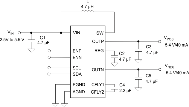
TPS65132 typ_app_slvsbm1.gif

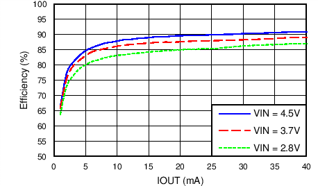
效率与输出电流间的关系

TPS65132 C003_SLVSBM1.png