JAJSE95A September   2017  – December 2017 ADS7142

PRODUCTION DATA.  

  1. 特長
  2. アプリケーション
  3. 概要
  4. 改訂履歴
  5. Pin Configuration and Functions
  6. Specifications
    1. 6.1  Absolute Maximum Ratings
    2. 6.2  ESD Ratings
    3. 6.3  Recommended Operating Conditions
    4. 6.4  Thermal Information
    5. 6.5  Electrical Characteristics - All Modes
    6. 6.6  Electrical Characteristics - Manual Mode
    7. 6.7  Electrical Characteristics - Autonomous Modes
    8. 6.8  Electrical Characteristics - High Precision Mode
    9. 6.9  Timing Requirements
    10. 6.10 Switching Characteristics
    11. 6.11 Typical Characteristics for All Modes
    12. 6.12 Typical Characteristics for Manual Mode
    13. 6.13 Typical Characteristics for Autonomous Modes
    14. 6.14 Typical Characteristics for High Precision Mode
  7. Detailed Description
    1. 7.1 Overview
    2. 7.2 Functional Block Diagram
    3. 7.3 Feature Description
      1. 7.3.1  Analog Input and Multiplexer
        1. 7.3.1.1 Two-Channel, Single-Ended Configuration
        2. 7.3.1.2 Single-Channel, Single-Ended Configuration
        3. 7.3.1.3 Single-Channel, Pseudo-Differential Configuration
      2. 7.3.2  OFFSET Calibration
      3. 7.3.3  Reference
      4. 7.3.4  ADC Transfer Function
      5. 7.3.5  Oscillator and Timing Control
      6. 7.3.6  I2C Address Selector
      7. 7.3.7  Data Buffer
        1. 7.3.7.1 Filling of the Data Buffer
        2. 7.3.7.2 Reading data from the Data Buffer
      8. 7.3.8  Accumulator
      9. 7.3.9  Digital Window Comparator
      10. 7.3.10 I2C Protocol Features
        1. 7.3.10.1 General Call
        2. 7.3.10.2 General Call with Software Reset
        3. 7.3.10.3 General Call with Write Software programmable part of slave address
        4. 7.3.10.4 Configuring Device into High Speed I2C mode
        5. 7.3.10.5 Bus Clear
      11. 7.3.11 Device Programming
        1. 7.3.11.1 Reading Registers
          1. 7.3.11.1.1 Single Register Read
          2. 7.3.11.1.2 Reading a Continuous Block of Registers
        2. 7.3.11.2 Writing Registers
          1. 7.3.11.2.1 Single Register Write
          2. 7.3.11.2.2 Set Bit
          3. 7.3.11.2.3 Clear Bit
          4. 7.3.11.2.4 Writing a continuous block of registers
    4. 7.4 Device Functional Modes
      1. 7.4.1 Device Power Up and Reset
      2. 7.4.2 Manual Mode
        1. 7.4.2.1 Manual Mode with CH0 Only
        2. 7.4.2.2 Manual Mode with AUTO Sequence
      3. 7.4.3 Autonomous Modes
        1. 7.4.3.1 Autonomous Mode with Threshold Monitoring and Diagnostics
          1. 7.4.3.1.1 Autonomous Mode with Pre Alert Data
          2. 7.4.3.1.2 Autonomous Mode with Post Alert Data
        2. 7.4.3.2 Autonomous Mode with Burst Data
          1. 7.4.3.2.1 Autonomous Mode with Start Burst
          2. 7.4.3.2.2 Autonomous Mode with Stop Burst
      4. 7.4.4 High Precision Mode
    5. 7.5 Optimizing Power Consumed by the Device
    6. 7.6 Register Map
      1. 7.6.1 RESET REGISTERS
        1. 7.6.1.1 WKEY Register (address = 17h), [reset = 00h]
        2. 7.6.1.2 DEVICE_RESET Register (address = 14h), [reset = 00h]
      2. 7.6.2 FUNCTIONAL MODE SELECT REGISTERS
        1. 7.6.2.1 OFFSET_CAL Register (address = 15h), [reset = 00h]
        2. 7.6.2.2 OPMODE_SEL Register (address = 1Ch), [reset = 00h]
        3. 7.6.2.3 OPMODE_I2CMODE_STATUS Register (address = 00h), [reset = 00h]
      3. 7.6.3 INPUT CONFIG REGISTER
        1. 7.6.3.1 CHANNEL_INPUT_CFG Register (address = 24h), [reset = 00h]
      4. 7.6.4 ANALOG MUX and SEQUENCER REGISTERS
        1. 7.6.4.1 AUTO_SEQ_CHEN Register (address = 20h), [reset = 03h]
        2. 7.6.4.2 START_SEQUENCE Register (address = 1Eh), [reset = 00h]
        3. 7.6.4.3 ABORT_SEQUENCE Register (address = 1Fh), [reset = 00h]
        4. 7.6.4.4 SEQUENCE_STATUS Register (address = 04h), [reset = 00h]
      5. 7.6.5 OSCILLATOR and TIMING CONTROL REGISTERS
        1. 7.6.5.1 OSC_SEL Register (address = 18h), [reset = 00h]
        2. 7.6.5.2 nCLK_SEL Register (address = 19h), [reset = 00h]
      6. 7.6.6 DATA BUFFER CONTROL REGISTER
        1. 7.6.6.1 DATA_BUFFER_OPMODE Register (address = 2Ch), [reset = 01h]
        2. 7.6.6.2 DOUT_FORMAT_CFG Register (address = 28h), [reset = 00h]
        3. 7.6.6.3 DATA_BUFFER_STATUS Register (address = 01h), [reset = 00h]
      7. 7.6.7 ACCUMULATOR CONTROL REGISTERS
        1. 7.6.7.1 ACC_EN Register (address = 30h), [reset = 00h]
        2. 7.6.7.2 ACC_CH0_LSB Register (address = 08h), [reset = 00h]
        3. 7.6.7.3 ACC_CH0_MSB Register (address = 09h), [reset = 00h]
        4. 7.6.7.4 ACC_CH1_LSB Register (address = 0Ah), [reset = 00h]
        5. 7.6.7.5 ACC_CH1_MSB Register (address = 0Bh), [reset = 00h]
        6. 7.6.7.6 ACCUMULATOR_STATUS Register (address = 02h), [reset = 00h]
      8. 7.6.8 DIGITAL WINDOW COMPARATOR REGISTERS
        1. 7.6.8.1  ALERT_DWC_EN Register (address = 37h), [reset = 00h]
        2. 7.6.8.2  ALERT_CHEN (address = 34h), [reset = 00h]
        3. 7.6.8.3  DWC_HTH_CH0_MSB Register (address = 39h), [reset = 00h]
        4. 7.6.8.4  DWC_HTH_CH0_LSB Register (address = 38h), [reset = 00h]
        5. 7.6.8.5  DWC_LTH_CH0_MSB Register (address = 3Bh), [reset = 00h]
        6. 7.6.8.6  DWC_LTH_CH0_LSB Register (address = 3Ah), [reset = 00h]
        7. 7.6.8.7  DWC_HYS_CH0 (address = 40h), [reset = 00h]
        8. 7.6.8.8  DWC_HTH_CH1_MSB Register (address = 3Dh), [reset = 00h]
        9. 7.6.8.9  DWC_HTH_CH1_LSB Register (address = 3Ch), [reset = 00h]
        10. 7.6.8.10 DWC_LTH_CH1_MSB Register (address = 3Fh), [reset = 00h]
        11. 7.6.8.11 DWC_LTH_CH1_LSB Register (address = 3Eh), [reset = 00h]
        12. 7.6.8.12 DWC_HYS_CH1 (address = 41h), [reset = 00h]
        13. 7.6.8.13 PRE_ALT_MAX_EVENT_COUNT Register (address = 36h), [reset = 00h]
        14. 7.6.8.14 ALERT_TRIG_CHID Register (address = 03h), [reset = 00h]
        15. 7.6.8.15 ALERT_LOW_FLAGS Register (address = 0C), [reset = 00h]
        16. 7.6.8.16 ALERT_HIGH_FLAGS Register (address = 0Eh), [reset = 00h]
  8. Application and Implementation
    1. 8.1 Application Information
    2. 8.2 Typical Applications
      1. 8.2.1 ADS7142 as a Programmable Comparator with False Trigger Prevention and Diagnostics
        1. 8.2.1.1 Design Requirements
          1. 8.2.1.1.1 Higher Power Consumption
          2. 8.2.1.1.2 Fixed Threshold Voltages
        2. 8.2.1.2 Detailed Design Procedure
          1. 8.2.1.2.1 Programmable Thresholds and Hysteresis
          2. 8.2.1.2.2 False Trigger Prevention with Event Counter
          3. 8.2.1.2.3 Fault Diagnostics with Data Buffer
        3. 8.2.1.3 Application Curve
      2. 8.2.2 Event-triggered PIR sensing with ADS7142
        1. 8.2.2.1 Design Requirements
        2. 8.2.2.2 Detailed Design Procedure
        3. 8.2.2.3 Application Curves
  9. Power-Supply Recommendations
    1. 9.1 AVDD and DVDD Supply Recommendations
  10. 10Layout
    1. 10.1 Layout Guidelines
    2. 10.2 Layout Example
  11. 11デバイスおよびドキュメントのサポート
    1. 11.1 ドキュメントのサポート
    2. 11.2 ドキュメントの更新通知を受け取る方法
    3. 11.3 コミュニティ・リソース
    4. 11.4 商標
    5. 11.5 静電気放電に関する注意事項
    6. 11.6 Glossary
  12. 12メカニカル、パッケージ、および注文情報

パッケージ・オプション

メカニカル・データ(パッケージ|ピン)
サーマルパッド・メカニカル・データ
発注情報

特長

  • コストの制約が厳しい設計用の、スタンドアロンのNanopowerセンサ・モニタ
  • 小さなパッケージ・サイズ: 1.5mm×2mm
  • 効率的なホストのスリープおよびウェークアップ
    • 900nWでの自律的モニタリング
    • イベント・トリガによるホスト・ウェークアップ用のウィンドウ付きコンパレータ
    • ホスト・スリープ時のデータ・バッファリング
  • センサの構成と較正が独立
    • デュアル・チャネル、疑似差動、またはグランド検出の入力構成
    • 較正のスレッショルドをプログラム可能
    • 内部的な較正によりオフセットとドリフト係数が改善
  • 誤ったトリガの防止
    • チャネルごとにスレッショルドをプログラム可能
    • ノイズ耐性のためヒステリシスをプログラム可能
    • 過渡除去用のイベント・カウンタ
  • ディープ・データ解析
    • フォルト診断用のデータ・バッファ
    • 16ビット精度用の高精度モード
    • 高速データ・キャプチャ用のワンショット・モード
  • I2C™インターフェイス
    • 1.65V~3.6Vまで互換
    • 8つの構成可能なアドレス
    • 最高3.4MHz (High Speed)
  • 広い動作範囲
    • アナログ電源: 1.65V~3.6V
    • 温度範囲: -40℃~+125℃

アプリケーション

  • モノのインターネット(IoT)のセンサ・ノード
  • ガス、熱、PIRモーション、および煙感知器
  • エレベータ、エスカレータ、HVAC、産業用機器などの予防保守
  • ウェアラブル・エレクトロニクス
  • フォルト・インジケータ用のゼロクロス検出
  • スーパーバイザ機能
  • コンパレータおよびプログラム可能な基準電圧
  • ディープ・ラーニング人工知能用のセンサ

概要

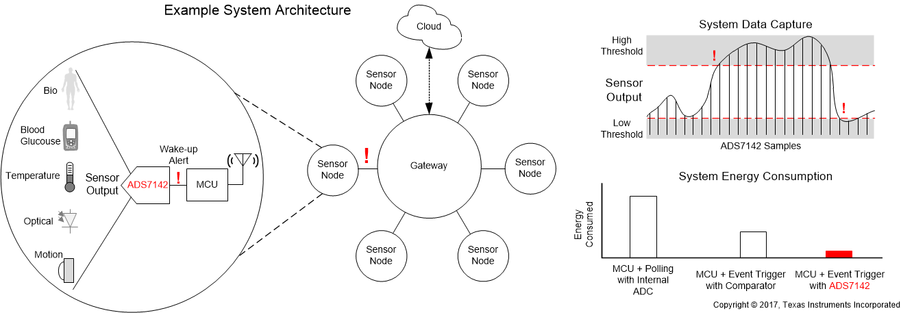
ADS7142は信号を自律的に監視し、同時にシステムの電力、信頼性、性能を最適化します。デジタル・ウィンドウ付きコンパレータを使用して、チャネルごとにイベント・トリガによる割り込みが実装されており、ハイおよびローのスレッショルド、ヒステリシス、およびイベント・カウンタをプログラム可能です。このデバイスでは、逐次比較型レジスタのアナログ/デジタル・コンバータ(SAR ADC)の前段にデュアル・チャネルのアナログ・マルチプレクサがあり、後段にセンサからデータを変換してキャプチャするための内部データ・バッファがあります。

ADS7142は10ピンのQFNパッケージで供給され、消費電力はわずか900nWです。外形が小さく、消費電力が低いため、このデバイスは容積が制限されている、またはバッテリ駆動のアプリケーションに適しています。

製品情報(1)

型番 パッケージ 本体サイズ(公称)
ADS7142 X2QFN (10) 1.50mm×2.00mm
  1. 利用可能なすべてのパッケージについては、このデータシートの末尾にある注文情報を参照してください。
ADS7142 FBD_06_SBAS773.gif