SLVSCW0 February 2015 UCD90240
PRODUCTION DATA.
- 1 Features
- 2 Applications
- 3 Description
- 4 Revision History
- 5 Pin Configuration and Functions
- 6 Specifications
-
7 Detailed Description
- 7.1 Device Overview
- 7.2 Functional Block Diagram
- 7.3
Feature Description
- 7.3.1 TI Fusion GUI
- 7.3.2 PMBUS Interface
- 7.3.3 Rail Setup
- 7.3.4 Rail Monitoring Configuration
- 7.3.5 GPI Configuration
- 7.3.6 Rail Sequence Configuration
- 7.3.7 Fault Responses Configuration
- 7.3.8 GPO Configuration
- 7.3.9 Margining Configuration
- 7.3.10 Pin Selected Rail States Configuration
- 7.3.11 Watchdog Timer
- 7.3.12 System Reset Function
- 7.3.13 Cascading Multiple Devices
- 7.3.14 Voltage Monitoring
- 7.3.15 Status Monitoring
- 7.3.16 Data and Error Logging to EEPROM Memory
- 7.3.17 Black Box First Fault Logging
- 7.3.18 PMBUS Address Selection
- 7.3.19 ADC Reference
- 7.3.20 Device Reset
- 7.3.21 Brownout
- 7.3.22 Device Configuration and Programming
- 7.3.23 Internal Fault Management
- 8 Application and Implementation
- 9 Power Supply Recommendations
- 10Layout
- 11Device and Documentation Support
- 12Mechanical, Packaging, and Orderable Information
1 Features
- Sequence, Monitor and Margin 24 Voltage Rails with a 9-mm × 9-mm Small Footprint
- Monitor and Respond to User-Defined Faults Including OV, UV, OC, UC, Temperature, Time-out, and GPI-Triggered Faults
- Flexible Sequence-on/off Dependencies, Delay Time, Boolean Logic, and GPIO Configuration to Support Complex Sequencing Applications
- High-accuracy Closed-loop Margining
- Active Trim Function Improves Rail Output Voltage Accuracy
- Advanced Nonvolatile Event Logging to Assist System Debugging
- Single-Event Fault Log (100 Entries)
- Peak Value Log
- Black Box Fault Log to Save Status of all Rails and I/O Pins at the First Fault
- Easily Cascade Up to 4 Power Sequencers and Take Coordinated Fault Responses
- Easy-to-Use Fusion GUIs Eliminate Coding Efforts
- Online and Offline System Level Design
- Online Monitoring and Debugging
- Manufacturing GUI Optimized for Manufacturers
- Programmable Watchdog Timer and System Reset
- Pin-Selected Rail State
- PMBus 1.2 Compliant
2 Applications
- Industrial and ATE
- Telecom and Networking Equipment
- Servers and Storage Systems
- Systems Requiring Sequencing and Monitoring of Multiple Power Rails
3 Description
The UCD90240 is a 24-rail PMBus addressable power sequencer and system manager in a compact 9-mm × 9-mm BGA package.
The device provides 24 analog monitor (MON) pins to monitor power-supply voltage, current, or temperature with two 12-bit ADC engines, 24 dedicated enable (EN) pins to control power rail on/off, 24 dedicated margin pins for closed-loop margining, 12 Logic GPO (LGPO) pins to support flexible Boolean logic and state machine functions, and 24 GPIO pins which can be configured as GPI, GPO, System Reset, cascading fault pins, and Watchdog I/O, and so forth.
The 24 EN pins and the 12 LGPO pins can be configured to be active driven or open-drain outputs.
Nonvolatile Event Logging preserves fault events after power dropout. Black Box Fault Log feature preserves the status of all rails and I/O pins when the first fault occurs.
The cascading feature offers convenient ways to manage up to 96 voltage rails through one SYNC_CLK pin connection. The Fault Pin feature coordinates among cascaded devices to take synchronized fault responses.
The Pin-Selected Rail States feature uses up to three GPIs to control up to eight user-defined power states. These states can implement system low-power modes as outlined in the Advanced Configuration and Power Interface (ACPI) specification.
The TI Fusion Digital Power™ designer software is an intuitive PC-based graphical user interface (GUI) that can configure, store, and monitor all system operating parameters.
Device Information(1)
| PART NUMBER | PACKAGE | BODY SIZE (NOM) |
|---|---|---|
| UCD90240 | BGA (157) | 9.00 mm × 9.00 mm |
- For all available packages, see the orderable addendum at the end of the data sheet.
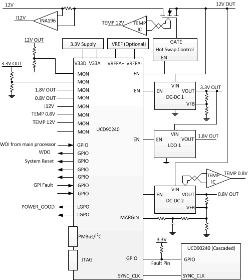
Simplified System Diagram

4 Revision History
| DATE | REVISION | NOTES |
|---|---|---|
| February 2015 | * | Initial release. |