SLUSCG9A February 2016 – March 2016
PRODUCTION DATA.
- 1 Features
- 2 Applications
- 3 Description
- 4 Revision History
- 5 Device Comparison Table
- 6 Pin Configuration and Functions
-
7 Specifications
- 7.1 Absolute Maximum Ratings
- 7.2 ESD Ratings
- 7.3 Recommended Operating Conditions
- 7.4 Thermal Information
- 7.5 Supply Current
- 7.6 Digital Input and Output DC Characteristics
- 7.7 Power-On Reset
- 7.8 2.5-V LDO Regulator
- 7.9 Internal Clock Oscillators
- 7.10 ADC (Temperature and Cell Measurement) Characteristics
- 7.11 Integrating ADC (Coulomb Counter) Characteristics
- 7.12 Data Flash Memory Characteristics
- 7.13 I2C-Compatible Interface Communication Timing Characteristics
- 7.14 SDQ Switching Characteristics
- 7.15 Typical Characteristics
- 8 Detailed Description
- 9 Application and Implementation
- 10Power Supply Recommendations
- 11Layout
- 12Device and Documentation Support
- 13Mechanical, Packaging, and Orderable Information
1 Features
- Battery Fuel Gauge For System-/Pack-Side Configuration
- Compensated End-of-Discharge Voltage (CEDV) Gauging Technology
- Adjusts for Battery Aging, Self-Discharge, Temperature, and Rate Changes
- Reports Remaining Capacity, State-of-Charge (SOC), and Time-to-Empty with Smoothing Filter
- Battery State-of-Health Estimation
- Supports Embedded or Removable Packs from 100-mAhr to 14,500-mAhr Capacity
- Accommodates Pack Swapping with up to Four Separate Battery Profiles
- Supports a Raw Coulomb Counter To Provide Delta Capacity Information
- Microcontroller Peripheral Supports:
- SDQ Communication Interface for
Authentication ID - 400-kHz I2C™ Serial Interface for High-Speed Communication
- 32 Bytes of Scratch-Pad FLASH NVM
- Battery Low Digital Output Warning
- Configurable SOC Interrupts
- External Thermistor, Internal Sensor, or Host Reported Temperature Options
- SDQ Communication Interface for
- 15-Pin 1.375 mm x 2.75 mm x 1.75 mm Pitch NanoFree™ (DSBGA) Package
2 Applications
- Smartphones, Feature Phones, and Tablets
- Wearables
- Building Automation
- Portable Medical/Industrial Handsets
- Portable Audio
- Gaming
3 Description
The Texas Instruments single-cell bq27320 battery fuel gauge requires very minimal configuration and system microcontroller firmware development, leading to quick system bring-up. The bq27320 uses the Compensated End-of-Discharge Voltage (CEDV) gas gauging algorithm for fuel gauging, and provides information such as remaining battery capacity (mAh), state-of-charge (%), runtime-to-empty (min), battery voltage (mV), temperature (°C) and state-of-health (%).
TI customers can tune chemistry parameters using TI's web-based tool, GAUGEPARCAL.
Configurable interrupts help save system power and free up the host from continuous polling. Accurate temperature sensing is supported via an external thermistor.
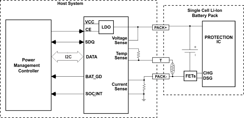
Battery fuel gauging with the bq27320 requires only PACK+ (P+), PACK– (P–), and optional thermistor (T) connections to a removable battery pack or embedded battery circuit. The device uses a 15-ball NanoFree™ (DSBGA) package. It is ideal for space-constrained applications.
Device Information(1)
| PART NUMBER | PACKAGE | BODY SIZE (NOM) |
|---|---|---|
| bq27320 | YZF (15) | 1.375 mm x 2.75 mm x 1.75 mm |
- For all available packages, see the orderable addendum at the end of the data sheet.
Simplified Schematic

4 Revision History
| DATE | REVISION | NOTES |
|---|---|---|
| March 2016 | A | PRODUCT PREVIEW to Production Data |