JAJSDZ7B March 2016 – October 2017
PRODUCTION DATA.
- 1 特長
- 2 アプリケーション
- 3 概要
- 4 改訂履歴
- 5 Pin Configuration and Functions
-
6 Specifications
- 6.1 Absolute Maximum Ratings
- 6.2 ESD Ratings
- 6.3 Recommended Operating Conditions
- 6.4 Thermal Information
- 6.5 Electrical Characteristics: Supply Current
- 6.6 Electrical Characteristics: Power Supply Control
- 6.7 Electrical Characteristics: AFE Power-On Reset
- 6.8 Electrical Characteristics: AFE Watchdog Reset and Wake Timer
- 6.9 Electrical Characteristics: Current Wake Comparator
- 6.10 Electrical Characteristics: VC1, VC2, VC3, VC4, BAT, PACK
- 6.11 Electrical Characteristics: SMBD, SMBC
- 6.12 Electrical Characteristics: PRES, BTP_INT, DISP
- 6.13 Electrical Characteristics: LEDCNTLA, LEDCNTLB, LEDCNTLC
- 6.14 Electrical Characteristics: Coulomb Counter
- 6.15 Electrical Characteristics: CC Digital Filter
- 6.16 Electrical Characteristics: ADC
- 6.17 Electrical Characteristics: ADC Digital Filter
- 6.18 Electrical Characteristics: CHG, DSG FET Drive
- 6.19 Electrical Characteristics: PCHG FET Drive
- 6.20 Electrical Characteristics: FUSE Drive
- 6.21 Electrical Characteristics: Internal Temperature Sensor
- 6.22 Electrical Characteristics: TS1, TS2, TS3, TS4
- 6.23 Electrical Characteristics: PTC, PTCEN
- 6.24 Electrical Characteristics: Internal 1.8-V LDO
- 6.25 Electrical Characteristics: High-Frequency Oscillator
- 6.26 Electrical Characteristics: Low-Frequency Oscillator
- 6.27 Electrical Characteristics: Voltage Reference 1
- 6.28 Electrical Characteristics: Voltage Reference 2
- 6.29 Electrical Characteristics: Instruction Flash
- 6.30 Electrical Characteristics: Data Flash
- 6.31 Electrical Characteristics: OCD, SCC, SCD1, SCD2 Current Protection Thresholds
- 6.32 Timing Requirements: OCD, SCC, SCD1, SCD2 Current Protection Timing
- 6.33 Timing Requirements: SMBus
- 6.34 Timing Requirements: SMBus XL
- 6.35 Typical Characteristics
-
7 Detailed Description
- 7.1 Overview
- 7.2 Functional Block Diagram
- 7.3
Feature Description
- 7.3.1 Primary (1st Level) Safety Features
- 7.3.2 Secondary (2nd Level) Safety Features
- 7.3.3 Charge Control Features
- 7.3.4 Gas Gauging
- 7.3.5 Configuration
- 7.3.6 Battery Parameter Measurements
- 7.3.7 Battery Trip Point (BTP)
- 7.3.8 Lifetime Data Logging Features
- 7.3.9 Authentication
- 7.3.10 LED Display
- 7.3.11 Voltage
- 7.3.12 Current
- 7.3.13 Temperature
- 7.3.14 Communications
- 7.4 Device Functional Modes
- 8 Applications and Implementation
- 9 Power Supply Recommendations
- 10Layout
- 11デバイスおよびドキュメントのサポート
- 12メカニカル、パッケージ、および注文情報
パッケージ・オプション
メカニカル・データ(パッケージ|ピン)
- RSM|32
サーマルパッド・メカニカル・データ
- RSM|32
発注情報
1 特長
- NチャネルFETドライブのハイサイド保護により、フォルト状況でもシリアル・バス通信が可能
- 内部バイパス付きのセル・バランス機能により、バッテリの状態を最適化
- 診断用の寿命データ・モニタと、障害解析用のブラック・ボックス・レコーダ
- プログラミング可能な各種の保護機能: 電圧、電流、温度
- JEITA充電アルゴリズムによりスマート充電をサポート
- 2つの独立したADCを持つアナログ・フロント・エンド
- 電流および電圧の同時サンプリング
- 入力オフセット誤差1µV未満(標準値)の高精度クーロン・カウンタ
- バッテリ・トリップ・ポイント(BTP)機能のサポートによる Windows®統合
- 充電状態およびバッテリ状態の表示用LEDディスプレイ
- 100kHz SMBus v1.1通信インターフェイスによるプログラミングとデータ・アクセス、400kHzモードにも対応
- SHA-1認証レスポンダによるバッテリ・パックのセキュリティ強化
- 小型の32ピンVQFNパッケージ(RSM)
2 アプリケーション
- ノートブックPC
- 医療用およびテスト機器
- ポータブル機器
- コードレス掃除機およびロボット掃除機
3 概要
補償付き放電終止電圧(CEDV)技術を採用したテキサス・インスツルメンツのbq4050デバイスは、高度に統合された高精度の1シリーズ~4シリーズ・セル用バッテリ残量計および保護ソリューションであり、自律的な充電制御とセル・バランスを実現します。
bq4050デバイスは、フラッシュをプログラム可能なカスタムのRISC (Reduced Instruction Set CPU)を搭載し、安全保護機能や、リチウムイオンおよびリチウムポリマ・バッテリ・パック用の認証機能を備えた、完全に統合されたパック・ベースのソリューションです。
bq4050バッテリ残量計はSMBus準拠のインターフェイスで通信を行い、超低消費電力かつ高速のTI bqBMPプロセッサ、高精度のアナログ測定機能、内蔵のフラッシュ・メモリ、ペリフェラルおよび通信ポートのアレイ、NチャネルFETドライブ、SHA-1認証変換レスポンダを組み合わせた、完全な高性能バッテリ管理ソリューションです。
製品情報(1)
| 型番 | パッケージ | 本体サイズ(公称) |
|---|---|---|
| bq4050 | VQFN (32) | 4.00mm×4.00mm |
- 利用可能なすべてのパッケージについては、このデータシートの末尾にある注文情報を参照してください。
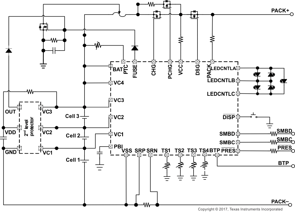
概略回路図
