JAJSDH3A March 2016 – July 2017 TAS5782M
PRODUCTION DATA.
- 1 特長
- 2 アプリケーション
- 3 概要
- 4 改訂履歴
- 5 Device Comparison Table
- 6 Pin Configuration and Functions
-
7 Specifications
- 7.1 Absolute Maximum Ratings
- 7.2 ESD Ratings
- 7.3 Recommended Operating Conditions
- 7.4 Thermal Information
- 7.5 Electrical Characteristics
- 7.6 Power Dissipation Characteristics
- 7.7 MCLK Timing
- 7.8 Serial Audio Port Timing - Slave Mode
- 7.9 Serial Audio Port Timing - Master Mode
- 7.10 I2C Bus Timing - Standard
- 7.11 I2C Bus Timing - Fast
- 7.12 SPK_MUTE Timing
- 7.13 Typical Characteristics
- 8 Parametric Measurement Information
-
9 Detailed Description
- 9.1 Overview
- 9.2 Functional Block Diagram
- 9.3
Feature Description
- 9.3.1 Power-on-Reset (POR) Function
- 9.3.2 Device Clocking
- 9.3.3
Serial Audio Port
- 9.3.3.1 Clock Master Mode from Audio Rate Master Clock
- 9.3.3.2 Clock Master from a Non-Audio Rate Master Clock
- 9.3.3.3 Clock Slave Mode with 4-Wire Operation (SCLK, MCLK, LRCK/FS, SDIN)
- 9.3.3.4 Clock Slave Mode with SCLK PLL to Generate Internal Clocks (3-Wire PCM)
- 9.3.3.5 Serial Audio Port - Data Formats and Bit Depths
- 9.3.3.6 Input Signal Sensing (Power-Save Mode)
- 9.3.4 Enable Device
- 9.3.5 Volume Control
- 9.3.6 Adjustable Amplifier Gain and Switching Frequency Selection
- 9.3.7
Error Handling and Protection Suite
- 9.3.7.1 Device Overtemperature Protection
- 9.3.7.2 SPK_OUTxx Overcurrent Protection
- 9.3.7.3 DC Offset Protection
- 9.3.7.4 Internal VAVDD Undervoltage-Error Protection
- 9.3.7.5 Internal VPVDD Undervoltage-Error Protection
- 9.3.7.6 Internal VPVDD Overvoltage-Error Protection
- 9.3.7.7 External Undervoltage-Error Protection
- 9.3.7.8 Internal Clock Error Notification (CLKE)
- 9.3.8 GPIO Port and Hardware Control Pins
- 9.3.9 I2C Communication Port
- 9.4 Device Functional Modes
- 10Application and Implementation
- 11Power Supply Recommendations
- 12Layout
-
13Register Maps
- 13.1
Registers - Page 0
- 13.1.1 Register 1 (0x01)
- 13.1.2 Register 6 (0x06)
- 13.1.3 Register 7 (0x07)
- 13.1.4 Register 8 (0x08)
- 13.1.5 Register 9 (0x09)
- 13.1.6 Register 12 (0x0C)
- 13.1.7 Register 13 (0x0D)
- 13.1.8 Register 14 (0x0E)
- 13.1.9 Register 15 (0x0F)
- 13.1.10 Register 16 (0x10)
- 13.1.11 Register 17 (0x11)
- 13.1.12 Register 18 (0x12)
- 13.1.13 Register 20 (0x14)
- 13.1.14 Register 21 (0x15)
- 13.1.15 Register 22 (0x16)
- 13.1.16 Register 23 (0x17)
- 13.1.17 Register 24 (0x18)
- 13.1.18 Register 27 (0x1B)
- 13.1.19 Register 28 (0x1C)
- 13.1.20 Register 29 (0x1D)
- 13.1.21 Register 30 (0x1E)
- 13.1.22 Register 32 (0x20)
- 13.1.23 Register 33 (0x21)
- 13.1.24 Register 34 (0x22)
- 13.1.25 Register 37 (0x25)
- 13.1.26 Register 40 (0x28)
- 13.1.27 Register 41 (0x29)
- 13.1.28 Register 42 (0x2A)
- 13.1.29 Register 43 (0x2B)
- 13.1.30 Register 44 (0x2C)
- 13.1.31 Register 59 (0x3B)
- 13.1.32 Register 60 (0x3C)
- 13.1.33 Register 61 (0x3D)
- 13.1.34 Register 62 (0x3E)
- 13.1.35 Register 63 (0x3F)
- 13.1.36 Register 64 (0x40)
- 13.1.37 Register 65 (0x41)
- 13.1.38 Register 67 (0x43)
- 13.1.39 Register 68 (0x44)
- 13.1.40 Register 69 (0x45)
- 13.1.41 Register 70 (0x46)
- 13.1.42 Register 71 (0x47)
- 13.1.43 Register 72 (0x48)
- 13.1.44 Register 73 (0x49)
- 13.1.45 Register 74 (0x4A)
- 13.1.46 Register 75 (0x4B)
- 13.1.47 Register 76 (0x4C)
- 13.1.48 Register 78 (0x4E)
- 13.1.49 Register 79 (0x4F)
- 13.1.50 Register 83 (0x53)
- 13.1.51 Register 85 (0x55)
- 13.1.52 Register 86 (0x56)
- 13.1.53 Register 87 (0x57)
- 13.1.54 Register 88 (0x58)
- 13.1.55 Register 91 (0x5B)
- 13.1.56 Register 92 (0x5C)
- 13.1.57 Register 93 (0x5D)
- 13.1.58 Register 94 (0x5E)
- 13.1.59 Register 95 (0x5F)
- 13.1.60 Register 108 (0x6C)
- 13.1.61 Register 119 (0x77)
- 13.1.62 Register 120 (0x78)
- 13.2 Registers - Page 1
- 13.1
Registers - Page 0
- 14デバイスおよびドキュメントのサポート
- 15メカニカル、パッケージ、および注文情報
1 特長
- 柔軟なオーディオI/O構成
- I2S、TDM、LJ、RJデジタル入力をサポート
- サンプル・レートのサポート
- BDアンプ変調
- 3線式のデジタル・オーディオ・インターフェイスをサポート(MCLK不要)
- 高性能のクローズド・ループ・アーキテクチャ(PVDD = 12V、RSPK = 8Ω、SPK_GAIN = 20dB)
- クローズド・ループによりコンポーネント数の削減と小さなソリューション・サイズを実現
- アイドル・チャネル・ノイズ = 62µVrms (A-Wtd)
- THD+N = 0.2% (1W、1kHzのとき)
- SNR = 103dB A-Wtd (THD+N = 1%を基準)
-
柔軟な処理機能
- 15 BiQuads/SmartEQ
- X-Over/EQ用の2×5 BiQuads
- 3バンドの高度なDRC + AGL
- 動的EQおよびSmartBass
- SFS (Sound Field Spatializer)
- 96kHzのプロセッサ・サンプリング
- 通信機能
- I2Cポートによるソフトウェア・モード制御
- 2つのアドレス選択ピン - 最大4デバイス
- 堅牢性および信頼性の特長
- クロック誤差、DC、および短絡保護
- 過熱および過電流からの保護機能
2 アプリケーション
- LCD、LED TV、多用途モニタ
- サウンド・バー、ドッキング・ステーション、PCオーディオ
- ワイヤレス・サブウーファー、Bluetoothスピーカ、アクティブ・スピーカ
3 概要
TAS5782Mデバイスは高性能のステレオ、クローズド・ループ、Class-Dアンプで、最高96kHzアーキテクチャのオーディオ・プロセッサが内蔵されています。デジタルからアナログへの変換を行うため、デバイスは高性能のDACと Burr Brown™オーディオ・テクノロジを使用します。必要な電源は、低電圧回路用のDVDD 1つと、高電圧回路用のPVDD 1つだけです。このデバイスは、標準のI2C通信を使用して、ソフトウェア制御ポートにより制御されます。
rDS(on)が90mΩの出力MOSFETにより、熱性能とデバイスのコストについて最良のバランスが達成されます。さらに、熱的に強化された48ピンTSSOPは、今日のコンシューマ向け電子機器にみられる高い周辺温度において、非常に優れた動作を実現します。
製品情報(1)
| 型番 | パッケージ | 本体サイズ(公称) |
|---|---|---|
| TAS5782M | TSSOP (48) | 12.50mm×6.10mm |
- 利用可能なすべてのパッケージについては、このデータシートの末尾にある注文情報を参照してください。
スペース
ブロック概略図

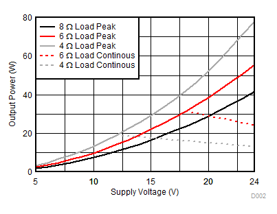
10% THD+Nでの電力とPVDDとの関係 (1)

1. TAS5782MEVMボードでのテスト結果