SLVSC27D July 2013 – October 2016 TPS65631W
PRODUCTION DATA.
- 1 Features
- 2 Applications
- 3 Description
- 4 Simplified Schematic
- 5 Revision History
- 6 Pin Configuration and Functions
- 7 Specifications
- 8 Detailed Description
- 9 Applications and Implementation
- 10Power Supply Recommendations
- 11Layout
- 12Device and Documentation Support
- 13Mechanical, Packaging, and Orderable Information
パッケージ・オプション
メカニカル・データ(パッケージ|ピン)
- DSK|10
サーマルパッド・メカニカル・データ
- DSK|10
発注情報
1 Features
- 2.9-V to 4.5-V Input Voltage Range
- Fixed 4.6-V Positive Output Voltage
- 0.5% VPOS Accuracy from 25ºC to 85ºC
- Separate VPOS Output Sense Pin
- Negative Output Voltage Digitally Programmable from –1.4 V to –4.4 V (–4 V Default)
- Output Currents up to 200 mA Supported
- Excellent Line Transient Regulation
- Outputs High Impedance During Shut Down
- Short-Circuit Protection
- Thermal Shutdown
- Available in 2.5-mm × 2.5-mm, 10-Pin QFN Package
2 Applications
AMOLED Displays
3 Description
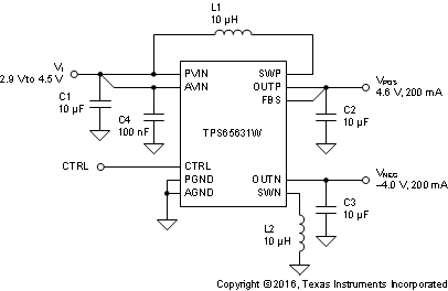
The TPS65631W is designed to drive AMOLED (Active Matrix Organic Light Emitting Diode) displays requiring positive and negative supply rails. The device integrates a boost converter for VPOS and an inverting buck boost converter for VNEG and is suitable for battery-operated products. The digital control pin (CTRL) allows programming the negative output voltage in digital steps. The TPS65631W uses a novel technology enabling excellent line transient performance.
Device Information(1)
| PART NUMBER | PACKAGE | BODY SIZE (NOM) |
|---|---|---|
| TPS65631W | QFN (10) | 2.50 mm × 2.50 mm |
- For all available packages, see the orderable addendum at the end of the data sheet
spacer
spacer
spacer
spacer
spacer
4 Simplified Schematic

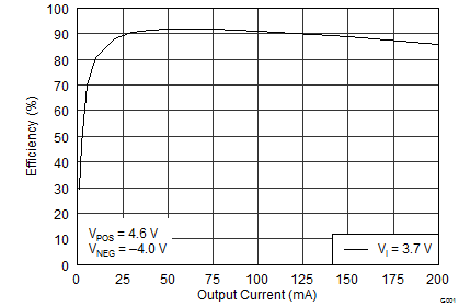
Efficiency vs Output Current
