SBOA170D october 2016 – april 2023 INA211 , INA211-Q1 , INA212 , INA212-Q1 , INA214 , INA214-Q1 , INA215 , INA215-Q1 , INA226 , INA226-Q1 , INA240-Q1 , INA250 , INA250-Q1 , INA253 , INA253-Q1 , INA254 , INA260 , INA301 , INA301-Q1 , INA302 , INA302-Q1 , INA303 , INA303-Q1
Current is one of the most common signals used for evaluating and diagnosing the operational effectiveness of an electronic system. However, measuring this signal directly is very challenging. Instead, many types of sensors are used to measure the proportional effects that occur due to current flowing throughout the system.
The most common sensing element used for detecting current flowing in a system is a resistor. Placing a resistor, called a shunt, in series with the current path develops a differential voltage across the resistor as current passes through it.
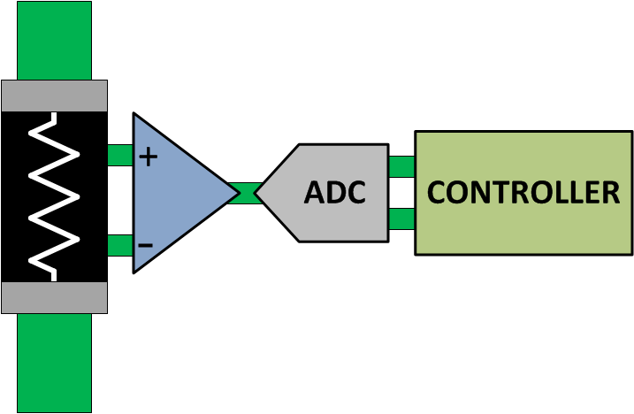
One common signal chain configuration for monitoring a current signal involves an analog front-end (AFE), an analog to digital converter (ADC), and a system controller as shown in Figure 1. An AFE, such as an operational amplifier or dedicated current sense amplifier, converts the small differential voltage developed across the shunt resistor to a larger output voltage that the ADC can digitize before sending the information to a controller. The system controller uses the current information to optimize the operational performance of the system or reduce functionality in the event of an out-of-range condition to prevent potential damaging conditions from occurring.
 Figure 1 Current Sensing Signal
Chain
Figure 1 Current Sensing Signal
ChainThe proper resistance value selection is critical in optimizing the signal chain path. The resistance value and corresponding voltage developed across the shunt results in a system power loss. To limit the power loss, minimize the shunt resistance. The resistor value is directly proportional to the signal developed and sent to the current sensing amplifier.
Amplifiers have fixed inherent errors associated with them, input offset voltage for example, that impact the measurement accuracy. As the input signal increases, the influence of these internal errors on the total measurement accuracy decreases. When the input signal decreases the corresponding measurement error is a higher. This relationship between the signal level and the acceptable measurement accuracy provides general lower limits for the current sensing resistor selection. Do not limit the upper limit value for the current sensing resistor based on the acceptable power loss of an application for this component.
One benefit of using resistors for current measurement is the availability of accurate components that provide both high precision and temperature stable measurements. Precision current sensing amplifiers are available featuring measurement capabilities optimized for interfacing with very small signals to accommodate small value resistors and low power losses.
There are two trends for resistors as the ohmic value decreases into the single digit mΩ level and below. One trend for this segment of resistors is the reduced package availability and resistor value combinations. The other trend is the increased cost for precision and low temperature coefficient components. Pairing a low ohmic, low temperature coefficient current sensing resistors with precision tolerance levels (about 0.1%) result in design costs in the several dollar range without including the cost associated with the precision amplifier.
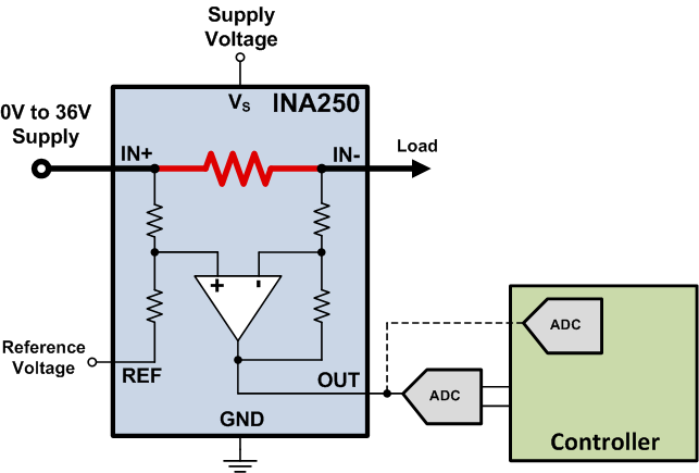
A component such as the INA250, shown in Figure 2, helps reduce the challenges of selecting these increased accuracy, higher cost resistors for applications needing precise and temperature stable measurements. This device pairs a precision, zero-drift, voltage output current sense amplifier with a 2-mΩ integrated current sensing resistor with a 0.1% maximum tolerance and a temperature drift of 15 ppm/°C over the entire temperature range of –40°C to +125°C. This device can accommodate continuous currents flowing through the onboard resistor of up to 15 A.
 Figure 2 Integrating The Current
Sensing Resistor
Figure 2 Integrating The Current
Sensing ResistorIn addition to the integrated precision resistor inside this device, the INA250 also addresses one of the most common issues associated with implementing a current sensing solution. A low-ohmic shunt resistor is used to reduce the current sensing power dissipation. A challenge in accommodating this low resistance value is the potential impact of parasitic resistance on the PCB. Parasitic resistance in series with the shunt resistor can cause additional measurement errors as current flows through the resistance to create the shunt voltage. The most common source for these measurement errors is poor layout techniques. A Kelvin connection, also known as a four terminal connection or a force-sense, is required to make sure that minimal additional resistance is present to alter the differential voltage developed between the input pins of the amplifier. There are PCB layout techniques to reduce the effect of parasitic resistance, however, this concern is removed with the INA250.
For applications that require measuring current in a high dv/dt common mode transients like motor control and solenoid control, the INA253 and INA254 is specifically design to reject PWM signals with a settling time of < 10 µs.
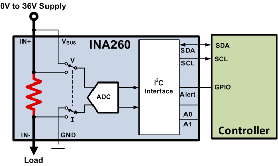
As previously described, the typical current sensing signal chain path includes the current sensing resistor, the analog front-end, ADC and system controller. The INA250 combines the shunt resistor and the current sensing amplifier. The INA260 combines the current sensing resistor, measurement front-end and the ADC into one single device.
Figure 3 shows the INA260 featuring the same precision, integrated sensing resistor, pairing it with a 16-bit, precision ADC optimized for current sensing applications. This combination provides an even higher performance measurement capability than the INA250 resulting in a maximum measurement gain error of 0.5% over the entire temperature range and a maximum input offset current of 5 mA.
 Figure 3 Integrated Signal Path
Pairing the precision, low-drift current sensing with these precision current sensing devices provides measurement solutions that are challenging to accomplish using discrete amplifier and resistor combinations. There are few catalog current sensing resistors available that are capable of enabling the combination of precision and temperature stable measurements but achieving this level of accuracy in a design size comparable to TSSOP-16 packaged integrated solutions does not exist.
Alternate Device Recommendations
For additional design flexibility, many stand-alone current sensing amplifiers and digital power monitors are also available. For lower performance applications with higher current requirements than the integrated solutions support, use the INA210 stand-alone current sensing amplifier. For applications requiring a stand-alone digital power monitor, use the INA226. For applications implementing overcurrent detection, the INA301 features an integrated comparator for on-chip overcurrent detection as fast as 1 μs.
| Device | Optimized Parameter | Performance Trade-Off |
|---|---|---|
| INA210 | 35 μV VOS, Package: SC70-6, QFN-10 | No onboard current sensing resistor |
| INA226 | 10 μV VOS, Package: MSOP-10 | No onboard current sensing resistor |
| INA301 | Signal Bandwidth, Onboard Comparator | No onboard current sensing resistor |