ZHCSEA4C May 2015 – December 2020 ADS54J40
PRODUCTION DATA
- 1 特性
- 2 应用
- 3 说明
- 4 Revision History
- 5 ADS54J40 Comparison
- 6 Pin Configuration and Functions
- 7 Specifications
-
8 Detailed Description
- 8.1 Overview
- 8.2 Functional Block Diagram
- 8.3 Feature Description
- 8.4 Device Functional Modes
- 8.5
Register Maps
- 8.5.1 Example Register Writes
- 8.5.2
Register Descriptions
- 8.5.2.1 General Registers
- 8.5.2.2
Master Page (080h) Registers
- 8.5.2.2.1 Register 20h (address = 20h), Master Page (080h)
- 8.5.2.2.2 Register 21h (address = 21h), Master Page (080h)
- 8.5.2.2.3 Register 23h (address = 23h), Master Page (080h)
- 8.5.2.2.4 Register 24h (address = 24h), Master Page (080h)
- 8.5.2.2.5 Register 26h (address = 26h), Master Page (080h)
- 8.5.2.2.6 Register 4Fh (address = 4Fh), Master Page (080h)
- 8.5.2.2.7 Register 53h (address = 53h), Master Page (080h)
- 8.5.2.2.8 Register 54h (address = 54h), Master Page (080h)
- 8.5.2.2.9 Register 55h (address = 55h), Master Page (080h)
- 8.5.2.2.10 Register 59h (address = 59h), Master Page (080h)
- 8.5.2.3 ADC Page (0Fh) Register
- 8.5.2.4
Main Digital Page (6800h) Registers
- 8.5.2.4.1 Register 0h (address = 0h), Main Digital Page (6800h)
- 8.5.2.4.2 Register 40h (address = 40h), Main Digital Page (6800h)
- 8.5.2.4.3 Register 41h (address = 41h), Main Digital Page (6800h)
- 8.5.2.4.4 Register 42h (address = 42h), Main Digital Page (6800h)
- 8.5.2.4.5 Register 43h (address = 43h), Main Digital Page (6800h)
- 8.5.2.4.6 Register 44h (address = 44h), Main Digital Page (6800h)
- 8.5.2.4.7 Register 4Bh (address = 4Bh), Main Digital Page (6800h)
- 8.5.2.4.8 Register 4Dh (address = 4Dh), Main Digital Page (6800h)
- 8.5.2.4.9 Register 4Eh (address = 4Eh), Main Digital Page (6800h)
- 8.5.2.4.10 Register 52h (address = 52h), Main Digital Page (6800h)
- 8.5.2.4.11 Register 68h (address = 68h), Main Digital Page (6800h)
- 8.5.2.4.12 Register 72h (address = 72h), Main Digital Page (6800h)
- 8.5.2.4.13 Register ABh (address = ABh), Main Digital Page (6800h)
- 8.5.2.4.14 Register ADh (address = ADh), Main Digital Page (6800h)
- 8.5.2.4.15 Register F7h (address = F7h), Main Digital Page (6800h)
- 8.5.2.5
JESD Digital Page (6900h) Registers
- 8.5.2.5.1 Register 0h (address = 0h), JESD Digital Page (6900h)
- 8.5.2.5.2 Register 1h (address = 1h), JESD Digital Page (6900h)
- 8.5.2.5.3 Register 2h (address = 2h), JESD Digital Page (6900h)
- 8.5.2.5.4 Register 3h (address = 3h), JESD Digital Page (6900h)
- 8.5.2.5.5 Register 5h (address = 5h), JESD Digital Page (6900h)
- 8.5.2.5.6 Register 6h (address = 6h), JESD Digital Page (6900h)
- 8.5.2.5.7 Register 7h (address = 7h), JESD Digital Page (6900h)
- 8.5.2.5.8 Register 16h (address = 16h), JESD Digital Page (6900h)
- 8.5.2.5.9 Register 31h (address = 31h), JESD Digital Page (6900h)
- 8.5.2.5.10 Register 32h (address = 32h), JESD Digital Page (6900h)
- 8.5.2.6
JESD Analog Page (6A00h) Registers
- 8.5.2.6.1 Register 12h (address = 12h), JESD Analog Page (6A00h)
- 8.5.2.6.2 Registers 13h-15h (addresses = 13h-5h), JESD Analog Page (6A00h)
- 8.5.2.6.3 Register 16h (address = 16h), JESD Analog Page (6A00h)
- 8.5.2.6.4 Register 17h (address = 17h), JESD Analog Page (6A00h)
- 8.5.2.6.5 Register 1Ah (address = 1Ah), JESD Analog Page (6A00h)
- 8.5.2.6.6 Register 1Bh (address = 1Bh), JESD Analog Page (6A00h)
- 8.5.2.7
Offset Read Page (JESD BANK PAGE SEL = 6100h, JESD BANK PAGE SEL1
= 0000h) Registers
- 8.5.2.7.1 Register 068h (address = 068h), Offset Read Page
- 8.5.2.7.2 Register 069h (address = 069h), Offset Read Page
- 8.5.2.7.3 Registers 074h, 076h, 078h, 7Ah (address = 074h, 076h, 078h, 7Ah), Offset Read Page
- 8.5.2.7.4 Registers 075h, 077h, 079h, 7Bh (address = 075h, 077h, 079h, 7Bh), Offset Read Page
- 8.5.2.8 Offset Load Page (JESD BANK PAGE SEL= 6100h, JESD BANK PAGE SEL1 = 0500h) Registers
- 9 Application Information Disclaimer
- 10Power Supply Recommendations
- 11Layout
- 12Device and Documentation Support
9.1.5 Idle Channel Histogram
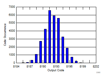
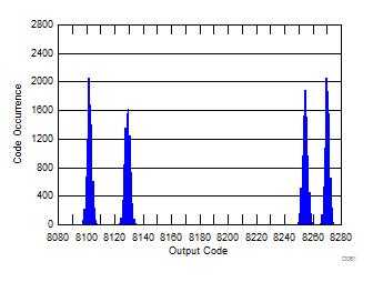
Figure 9-6 shows a histogram of output codes for when no signal is applied at the analog inputs of the ADS54J40 . Figure 9-7 shows that when the dc offset correction block of the device is bypassed, the output code histogram becomes multi-modal with as many as four peaks because the ADS54J40 is a 4-way interleaved ADC with each ADC core having a different internal dc offset.
 Figure 9-6 Idle Channel Histogram (No
Signal at Analog Inputs, DC Offset Correction is On)
 Figure 9-7 Idle Channel Histogram (No
Signal at Analog Inputs, DC Offset Correction is Off)
Figure 9-7 Idle Channel Histogram (No
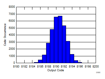
Signal at Analog Inputs, DC Offset Correction is Off)Figure 9-8 shows that when the dc offset correction block is frozen (instead of bypassed), the output code histogram improves (compared to when bypassed). However, when the temperature changes, the dc offset difference among interleaving cores may increase resulting in increased spacing between peaks in the histogram.
 Figure 9-8 Idle Channel Histogram (No
Signal at Analog Inputs, DC Offset Correction is Frozen)