SCHS023E November 1998 – September 2016 CD4013B
PRODUCTION DATA.
- 1 Features
- 2 Applications
- 3 Description
- 4 Revision History
- 5 Pin Configuration and Functions
- 6 Specifications
- 7 Detailed Description
- 8 Application and Implementation
- 9 Power Supply Recommendations
- 10Layout
- 11Device and Documentation Support
- 12Mechanical, Packaging, and Orderable Information
封装选项
请参考 PDF 数据表获取器件具体的封装图。
机械数据 (封装 | 引脚)
- D|14
- PW|14
- N|14
- NS|14
散热焊盘机械数据 (封装 | 引脚)
订购信息
8 Application and Implementation
NOTE
Information in the following applications sections is not part of the TI component specification, and TI does not warrant its accuracy or completeness. TI’s customers are responsible for determining suitability of components for their purposes. Customers should validate and test their design implementation to confirm system functionality.
8.1 Application Information
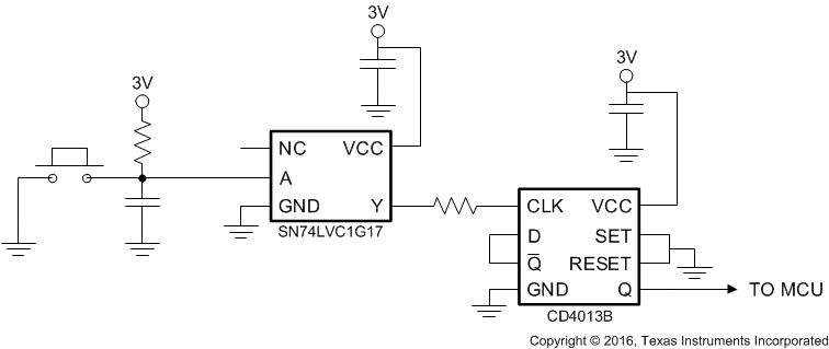
A high level at the SET or RESET inputs sets or resets the outputs, regardless of the levels of the other inputs. When SET and RESET are inactive (low), data at the data (D) input meeting the setup time requirements is transferred to the outputs on the positive-going edge of the clock pulse. Clock triggering occurs at a voltage level and is not related directly to the rise time of the clock pulse. Following the hold-time interval, data at the D input can be changed without affecting the levels at the outputs. The resistor and capacitor at the RESET pin are optional. If they are not used, the RESET and SET pin must be connected directly to ground to be inactive.
8.2 Typical Application
 Figure 9. Power Button Circuit
8.2.1 Design Requirements
Input signals must be designed and implemented so that they do not exceed the voltage level of the power supply.
8.2.2 Detailed Design Procedure
The recommended input conditions for this application example includes rise time and fall time specifications (see Δt/ΔV in Recommended Operating Conditions) and specified high and low levels (see VIH and VIL in Recommended Operating Conditions). Inputs are not overvoltage tolerant and must be below VCC level because of the presence of input clamp diodes to VCC. The recommended output condition for the CD4013B application includes specific load currents. Load currents must be limited so as to not exceed the total power (continuous current through VCC or GND) for the device. These limits are located in Absolute Maximum Ratings. Outputs must not be pulled above VCC.
8.2.3 Application Curve
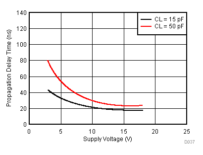
 Figure 10. Typical Transition Time vs Load Capacitance