ZHCSKQ2B January 2020 – January 2021 LM5156-Q1 , LM51561-Q1
PRODUCTION DATA
- 1 特性
- 2 应用
- 3 说明
- 4 Revision History
- 5 Description (continued)
- 6 Device Comparison Table
- 7 Pin Configuration and Functions
- 8 Specifications
-
9 Detailed Description
- 9.1 Overview
- 9.2 Functional Block Diagram
- 9.3
Feature Description
- 9.3.1 Line Undervoltage Lockout (UVLO/SYNC/EN Pin)
- 9.3.2 High Voltage VCC Regulator (BIAS, VCC Pin)
- 9.3.3 Soft Start (SS Pin)
- 9.3.4 Switching Frequency (RT Pin)
- 9.3.5 Dual Random Spread Spectrum (DRSS)
- 9.3.6 Clock Synchronization (UVLO/SYNC/EN Pin)
- 9.3.7 Current Sense and Slope Compensation (CS Pin)
- 9.3.8 Current Limit and Minimum On-time (CS Pin)
- 9.3.9 Feedback and Error Amplifier (FB, COMP Pin)
- 9.3.10 Power-Good Indicator (PGOOD pin)
- 9.3.11 Hiccup Mode Overload Protection (LM51561-Q1 Only)
- 9.3.12 Maximum Duty Cycle Limit and Minimum Input Supply Voltage
- 9.3.13 MOSFET Driver (GATE Pin)
- 9.3.14 Overvoltage Protection (OVP)
- 9.3.15 Thermal Shutdown (TSD)
- 9.4 Device Functional Modes
- 10Application and Implementation
- 11Power Supply Recommendations
- 12Layout
- 13Device and Documentation Support
- 14Mechanical, Packaging, and Orderable Information
9.3.7 Current Sense and Slope Compensation (CS Pin)
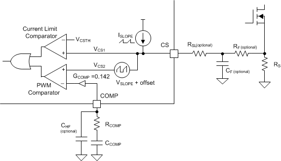
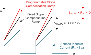
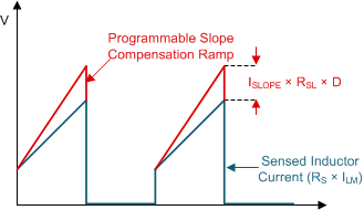
The device has a low-side current sense and provides both fixed and optional programmable slope compensation ramps, which help prevent subharmonic oscillation at high duty cycle. Both fixed and programmable slope compensation ramps are added to the sensed inductor current input for the PWM operation. But, only the programmable slope compensation ramp is added to the sensed inductor current input (see Figure 9-18). For an accurate peak current limit operation over the input supply voltage, TI recommends using only the fixed slope compensation (see Figure 8-5).
The device can generate the programmable slope compensation ramp using an external slope resistor (RSL) and a sawtooth current source with a slope of 30 μA × fRT. This current flows out of the CS pin.
 Figure 9-18 Current Sensing and Slope Compensation
 Figure 9-19 Slope Compensation Ramp
(a) at PWM Comparator Input
 Figure 9-20 Slope Compensation Ramp
(b) at Current Limit Comparator Input
Figure 9-20 Slope Compensation Ramp
(b) at Current Limit Comparator InputUse Equation 6 to calculate the value of the peak slope current (ISLOPE) and use Equation 7 to calculate the value of the peak slope voltage (VSLOPE).


where
- fSYNC = fRT if clock synchronization is not used.
According to peak current mode control theory, the slope of the compensation ramp must be greater than half of the sensed inductor current falling slope to prevent subharmonic oscillation at high duty cycle. Therefore, the minimum amount of slope compensation in boost topology should satisfy the following inequality:

where
- VF is a forward voltage drop of D1, the external diode.
The recommended margin to cover non-ideal factors is 1.2. If required, RSL can be added to further increase the slope of the compensation ramp. Typically 82% of the sensed inductor current falling slope is known as an optimal amount of the slope compensation. The RSL value to achieve 82% of the sensed inductor current falling slope is calculated as shown in Equation 9.

If clock synchronization is not used, the fSW frequency equals the fRT frequency. If clock synchronization is used, the fSW frequency equals the fSYNC frequency. The maximum value for the RSL resistance is 2 kΩ.