ZHCSM05 June 2020 LM51561H-Q1 , LM5156H-Q1
PRODUCTION DATA
- 1 特性
- 2 应用
- 3 说明
- 4 Revision History
- 5 说明(续)
- 6 Device Comparison Table
- 7 Pin Configuration and Functions
- 8 Specifications
-
9 Detailed Description
- 9.1 Overview
- 9.2 Functional Block Diagram
- 9.3
Feature Description
- 9.3.1 Line Undervoltage Lockout (UVLO/SYNC/EN Pin)
- 9.3.2 High Voltage VCC Regulator (BIAS, VCC Pin)
- 9.3.3 Soft Start (SS Pin)
- 9.3.4 Switching Frequency (RT Pin)
- 9.3.5 Dual Random Spread Spectrum (DRSS)
- 9.3.6 Clock Synchronization (UVLO/SYNC/EN Pin)
- 9.3.7 Current Sense and Slope Compensation (CS Pin)
- 9.3.8 Current Limit and Minimum On-time (CS Pin)
- 9.3.9 Feedback and Error Amplifier (FB, COMP Pin)
- 9.3.10 Power-Good Indicator (PGOOD Pin)
- 9.3.11 Hiccup Mode Overload Protection (LM51561H-Q1 Only)
- 9.3.12 Maximum Duty Cycle Limit and Minimum Input Supply Voltage
- 9.3.13 MOSFET Driver (GATE Pin)
- 9.3.14 Overvoltage Protection (OVP)
- 9.3.15 Thermal Shutdown (TSD)
- 9.4 Device Functional Modes
- 10Application and Implementation
- 11Power Supply Recommendations
- 12Layout
- 13Device and Documentation Support
- 14Mechanical, Packaging, and Orderable Information
3 说明
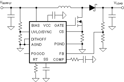
LM5156xH-Q1(LM5156H-Q1 和 LM51561H-Q1)器件是采用峰值电流模式控制、具有宽输入范围的非同步升压控制器。该器件可用于升压、SEPIC 和反激式拓扑。
如果 BIAS 引脚连接到 VCC 引脚,该器件可由单节电池(最低电压 2.97V)启动。如果 BIAS 引脚电压高于 3.5V,则该器件可使用低至 1.5V 的输入电源电压。
器件信息
| 器件型号 | 封装(1) | 封装尺寸(标称值) |
|---|---|---|
| LM5156xH-Q1 | HTSSOP (14) | 5.0mm × 4.4mm |
(1) 如需了解所有可用封装,请参阅数据表末尾的可订购米6体育平台手机版_好二三四附录。
 典型升压应用