ZHCSCU3C January 2014 – September 2019 TCA5013
PRODUCTION DATA.
- 1 特性
- 2 应用
- 3 说明
- 4 修订历史记录
- 5 Pin Configuration and Functions
-
6 Specifications
- 6.1 Absolute Maximum Ratings
- 6.2 Handling Ratings
- 6.3 Recommended Operating Conditions
- 6.4 Thermal Information
- 6.5 Electrical Characteristics—Power Supply and ESD
- 6.6 Electrical Characteristics—Card VCC
- 6.7 Electrical Characteristics—Card RST
- 6.8 Electrical Characteristics—Card CLK
- 6.9 Electrical Characteristics—Card Interface IO, C4 and C8
- 6.10 Electrical Characteristics—PRES
- 6.11 Electrical Characteristics—IOMC1 and IOMC2
- 6.12 Electrical Characteristics—CLKIN1 and CLKIN2
- 6.13 Electrical Characteristics—A0 and SHDN
- 6.14 Electrical Characteristics—INT
- 6.15 Electrical Characteristics—GPIO
- 6.16 Electrical Characteristics—SDA and SCL
- 6.17 Electrical Characteristics—Fault Condition Detection
- 6.18 I2C Interface Timing Requirements
- 6.19 I2C Interface Timing Characteristics
- 6.20 Synchronous Type 1 Card Activation Timing Characteristics
- 6.21 Synchronous Type 2 Card Activation Timing Characteristics
- 6.22 Card Deactivation Timing Characteristics
- 6.23 Typical Characteristics
- 7 Parameter Measurement Information
-
8 Detailed Description
- 8.1 Overview
- 8.2 Functional Block Diagram
- 8.3 Feature Description
- 8.4 Device Functional Modes
- 8.5 Programming
- 8.6 Register Maps
- 9 Application and Implementation
- 10Power Supply Recommendations
- 11Layout
- 12器件和文档支持
- 13机械、封装和可订购信息
8.4.10.3 LDOs and Load Transient Response
The TCA5013 has an internal LDO that generates a stable supply for the internal circuits. The input to the internal LDO is VDD. The output of the internal LDO is connected to the LDOCAP pin. A 1 uF decoupling capacitor shall be connected to the LDOCAP pin to ensure proper device operation. The internal LDO voltage is typically 2.65 V but can be lower if VDD is not sufficient.
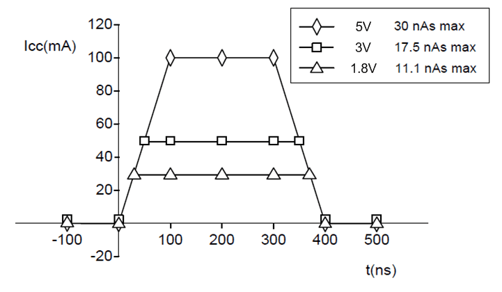
In addition to the internal LDO, the TCA5013 has a dedicated LDO per card interface to generate the VCC for that card interface (here on forth, these LDOs are referred to as card LDOs). The card LDOs provide the power supply for smartcard operation. During the normal operation of the smartcard, the LDO output is subject to load transients. The EMV4.3 standard defines a load transient envelope shown in Figure 19. The card LDOs are able to handle these transients, while keeping VCC within limits defined in Electrical Characteristics—Card VCC. An external 200 nF capacitor shall be connected to their card VCC pins (VCCUC, VCCCS1, VCCS2, VCCS3) to ensure proper load transient response by the card LDOs.
 Figure 19. Load Transients defined by EMV4.3
 The card LDOs are enabled only when the card interface is activated (see Active Mode). The output voltage is determined by the card interface settings registers (Reg 0x01, Reg 0x11, Reg 0x21, Reg 0x31). At the start of the activation sequence, the card LDO is enabled and starts to ramp to the voltage defined in the corresponding card interface settings register. Once the LDO has been enabled, any changes to the card interface settings registers will not have any effect on the LDO output voltage. The card also LDOs also have short circuit protection. When the current drawn exceeds ~150 mA (typ.) the LDO automatically shuts down and the card interface is deactivated (see Deactivation Sequence).