SBOA510 March 2021 OPA455 , OPA462
- Trademarks
- 1Introduction
- 2Three Op Amp OPA462 HV Solution
- 3Lower Voltage, Lower Cost Three Op Amp Solution
- 4OPA462 300 Vpp Output Solution With Discrete Transistor Supply-Rail Drivers
- 5Lessons Learned from the Practical Implementation of the HV Op Amp Solutions
-
A Appendix
- A.1 Overview
- A.2 Summary of Results
- A.3 Test Setup and Equipment
- A.4 Printed Circuit Boards
- A.5 Power Supply, Source Measurement Unit (SMU)
- A.6 Arbitrary Waveform Generator (AWG)
- A.7 Oscilloscope
- A.8 Circuit 1: OPA462 Three op amp Solution
- A.9 Circuit 2: Lower Voltage, Lower Cost Three Op Amp Solution
- A.10 Circuit 3: OPA462 300 Vpp Output Solution With Discrete Transistor Supply-Rail Drivers
A.4 Printed Circuit Boards
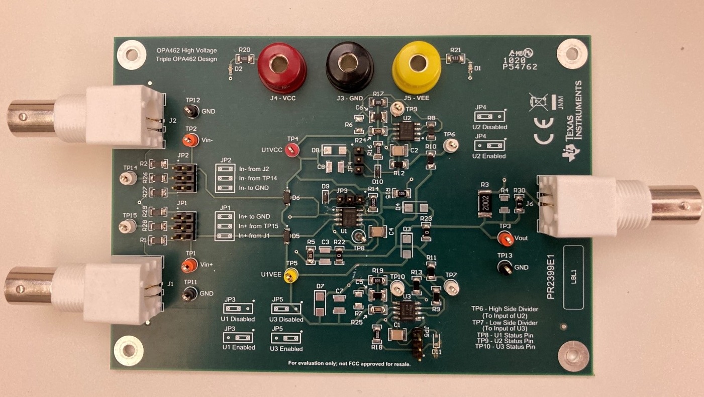
The schematic used in testing each circuit is shown in the appropriate section. A custom PCB was created for each of the designs, reducing the parasitics associated with breadboarding or other prototyping techniques. As an example, Figure 6-2 shows one of the test boards built for the OPA462 Rail Drivers design. Jumpers permitted quick and easy reconfiguration of the board between tests.
Please note that Texas Instruments does not make available finished PC board assemblies, PC boards or the artwork for these test PCBs. These were developed for our internal use only.
 Figure 6-2 Example Test PCB Development for
OPA462 Three Op Amp Rail Drivers Circuit