SLAA842B December 2018 – August 2019 DS90C401 , DS90C402 , MSP430FR2512 , MSP430FR2522 , MSP430FR2532 , MSP430FR2533 , MSP430FR2632 , MSP430FR2633 , MSP430FR2672 , MSP430FR2673 , MSP430FR2675 , MSP430FR2676
7 Step 5: Firmware Development and System Tuning
The 5th step of designing a successful capacitive touch sensing system is to develop the firmware with the optimized tuning configuration based on the system requirements defined in Step 2 and the hardware developed in Step 4.
TI provides two software development tools that can reduce firmware development effort and time. Download the latest version of the tools.
- CapTIvate Design Center Tool (Download)
- Code Composer Studio IDE (Download)
- IAR Embedded Workbench for MSP430 IDE (Download)
or
Step 5a: CapTIvate Design Center
The CapTIvate Design Center is a rapid development tool that accelerates capacitive touch designs for CapTIvate Technology enabled MSP430 devices. By helping guide you through the capacitive touch development process, the CapTIvate Design Center can simplify accelerate any touch design through the use of innovative user graphical interfaces, wizards and controls. This GUI tool can generate the source code, perform real time tunning and also provide example projects.
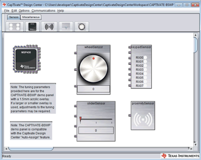 Figure 18. CapTIvate Design Center
 Step 5b: CapTIvate Tuning Process
It is important to first understand how to leverage the software development tools to tune the sensor and then how to actually tune the sensor performance step by step.
 Figure 19. CapTIvate Tuning Process
 Step 5b.1: Create the Project
- Use CapTIvate Design Center to drag and drop capacitive sensing elements to the GUI workspace based on the hardware design.
- Use auto-assign or manually assign the sensor connections to MSP430 capacitive touch I/O pins based on your schematic and layout.
- Select the I2C or UART communication interface to the host PC.
Refer to Create a new project for details.
Step 5b.2: Generate Source Code
Refer to Generate source code for details.
Step 5b.3: Program Source Code to MCU
Refer to Loading and running generated projects for details.
Step 5b.4: Real-Time Tuning and Configuring
After connecting the target MCU to CapTIvate Design Center GUI tool you should be able to display the real-time sensor data, and also to enable reading and modifying the sensor’s configuration and tuning parameters.
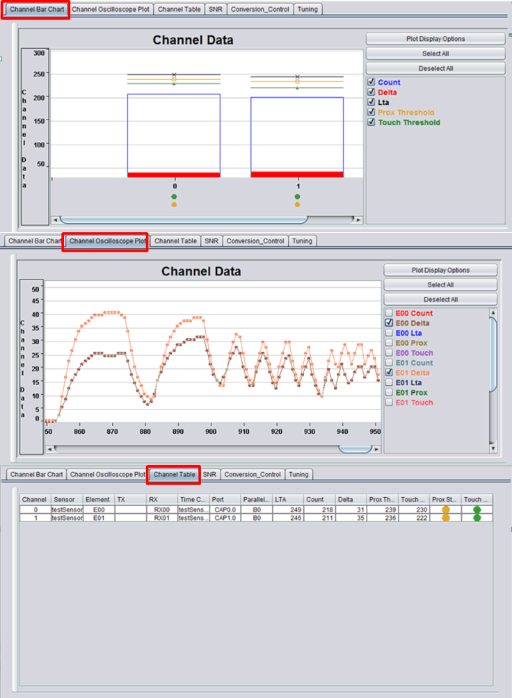 Figure 20. Sensor Parameters
 Open the Sensor Properties window by double clicking the sensor element.
 Figure 21. Sensor Properties Window
 Open the Controller Properties window by double clicking the controller element.
 Figure 22. Controller Properties Window
 NOTE
Make sure to enable the advance mode to see all the tuning parameters that are listed in this document. In CapTIvate Design Center, click Options → Features → Advanced → OK (See Figure 23).
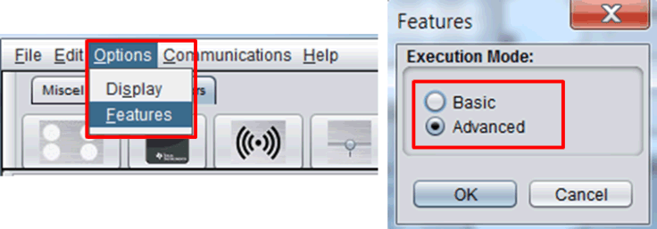 Figure 23. Enable Advanced Mode
 Three key areas determine the capacitive touch performance. The purpose of the tuning process is to balance the performance tradeoffs in these three areas.
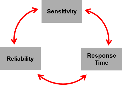 Figure 24. Tuning Consideration
 Sensitivity Tuning Checklist
Table 13. Sensitivity Tuning Checklist
| No. | Parameter | Location | Recommendations |
|---|---|---|---|
| 1 | Conversion Gain | Sensor Properties → Conversion_Control | 100 |
| 2 | Conversion Count | Sensor Properties → Conversion_Control | Depends on the sensor and mechanical design. Start from the small number and increase it until reach the desired touch delta. |
| 3 | Frequency Divider | Sensor Properties → Conversion_Control | Self capacitance: f/4
Mutual capacitance: f/2 |
| 4 | Delta | Sensor Properties → Channel Table | Desired touched delta depends on applications |
1 and 2. Conversion Gain and Conversion Count
- Conversion Gain and Conversion Count are the fundamental parameters used to establish the sensitivity of the sensor. They are used to adjust the resolution and sensitivity of the sensor.
- Conversion Gain should be set to 100 (Min) for most of the applications.
- Conversion Count should be adjusted starting from the small number and increasing until it reaches the desired touch delta.
- The typical touch delta for buttons is 50 and for sliders and wheels is 50 to 100.
- These two parameters apply to all of the sensor elements in this sensor group.
3. Frequency Divider
- The conversion frequency divider allows for the conversion clock to be divided down from the base rate of 16 MHz. The conversion clock period must be long enough to ensure complete charge transfer phases.
- In typical designs, self-capacitance frequency divider should be set to f/4 and mutual capacitance frequency divider should be set to f/2.
4. Delta
- Delta typically refers to the change in a measurement due to change in capacitance of an electrode caused by a proximity or touch condition.
Delta = Signal Count – Long Term Average (LTA) - Long Term Average (LTA) is the baseline count of the sensing signal.
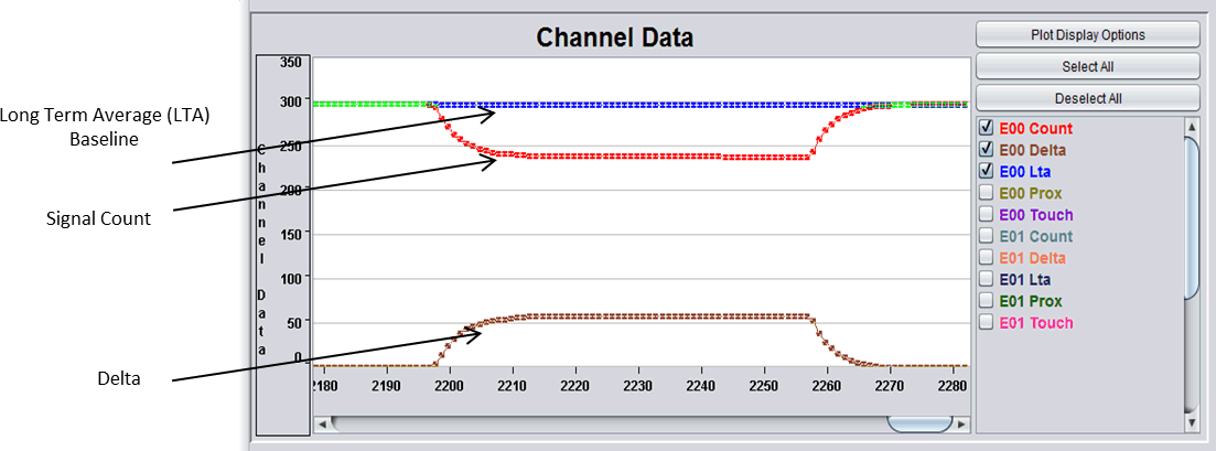 Figure 25. Delta
 Table 14 is a reliability tuning checklist.
Table 14. Reliability Tuning Checklist
| No. | Parameter | Location | Recommendations |
|---|---|---|---|
| 1 | Prox Threshold | Sensor Properties → Tuning | This proximity threshold is an absolute value of the counts not percentage. The value depends on applications. |
| 2 | Touch Threshold | Sensor Properties → Tuning | This touch threshold is a percentage value of LTA. The value depends on the PCB and overlay design. |
| 3 | Signal-to-Noise Ratio Measurement | Sensor Properties → SNR | Run SNR measurement before moving forward
Make sure Advice = GOOD |
| 4 | Prox Debounce | Sensor Properties → Tuning | Debounce In = 1
Debounce Out = 1 |
| 5 | Touch Debounce | Sensor Properties → Tuning | Debounce In = 2
Debounce Out = 2 |
| 6 | Noise Immunity | Controller Properties → Compile Time Options | If noisy environment and system → enable noise immunity |
| 7 | Error Threshold | Sensor Properties → Tuning | Long term average (LTA) x 2 |
| 8 | Sensor Timeout Threshold | Sensor Properties → Tuning | 65535 (off) or depends on application |
| 9 | Count Filter Beta | Sensor Properties → Tuning | 1 or 2 |
| 10 | LTA Filter Beta | Sensor Properties → Tuning | 7 |
1. Prox Threshold
- This is used to set the level of interaction required by the user for proximity detection.
- If the application is proximity detection, put your hand at the distance where proximity detection should trigger. Record the delta for that sensor and set the Prox Threshold to be the delta. Also makes sure the Prox Threshold is larger than the delta caused by the noise.
- If the application is only touch detection, just need to make sure the Prox Threshold is larger than the noise caused delta and also larger than the Touch Threshold delta.
 Figure 26. Proximity Threshold
 2. Touch Threshold
- This is used to set the level of interaction required by the user for touch detection.
- It is a percentage of the Longer Term Average (LTA) baseline value. And it depends on the PCB and overlay design.
- You can select the Touch Threshold for individual elements in a sensor group.
 Figure 27. Touch Threshold
  Figure 28. Change Touch Threshold
 3. SNR Measurement
- After you completed the Sensitivity Tuning Checklist and set the Prox Threshold and Touch Threshold. Using the SNR Measurement tool to check the system reliability based on the tuning parameters. This is a critical step of the tuning process.
- Make sure the advice from the tool is GOOD and then move on to the tuning process. Otherwise, go back to adjust the tuning parameters or change the hardware design. Refer to Sensitivity, SNR, and Design Margin in Capacitive Touch Applications for details.
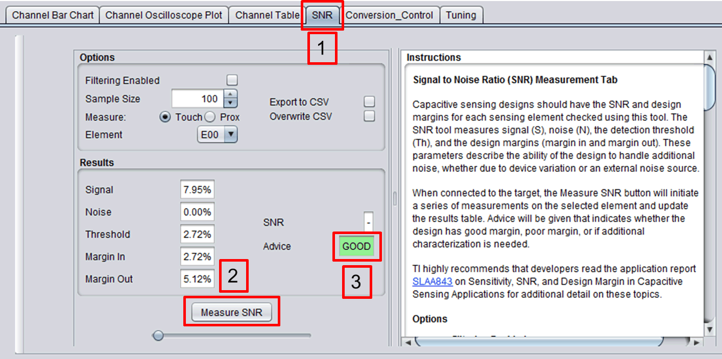 Figure 29. SNR Measurement
 4 and 5. Prox Debounce and Touch Debounce
- They are used to select the number of consecutive samples that the sensor must be in detection to generate a detection state to the system. This is to prevent transient noise signal to cause false touch detections.
- The Touch Debounce parameters are generally set to 2 for reliable sensor status detection. This value can be raised or lowered based on the noise aspects of the system.
 Figure 30. Proximity and Touch Debounce
 6. Noise Immunity
Based on the operating conditions defined in Step 2, if the application requires noise immunity feature, you can enable the software noise immunity feature in CapTIvate Design Center. Refer to Noise Immunity Tuning Check List for details.
Table 15 is a response time tuning checklist.
Table 15. Response Time Tuning Checklist
| No. | Parameter | Location | Recommendations |
|---|---|---|---|
| 1 | Active Mode Scan Rate (ms) | Controller Properties → Conversion Control | Typical HMI application, 33 ms (30 Hz) |
| 2 | Scan Time Estimation | Controller Properties → Scan Time Estimation | |
| 3 | Touch Debounce | Sensor Properties → Tuning | Debounce in = 2
Debounce out = 1 |
1. Active Mode Scan Rate
- The active mode scan rate specifies the period (in milliseconds) to refresh the user interface at when in active mode.
- To convert to samples per second (sps), divide 1000 by the specified scan rate period. For example, a scan rate of 50 ms equates to 20 sps.
- A shorter scan rate period increases application response rate, but the tradeoff is higher power consumption. Typical HMI applications use a scan period of 33 ms (30 Hz).
2. Scan Time Estimation
Make sure the scan rate period is longer than the time takes to scan all the sensors. This window shows the estimated:
- Time takes to scan each sensor
- Time takes to scan all the sensors
- Scan rate period
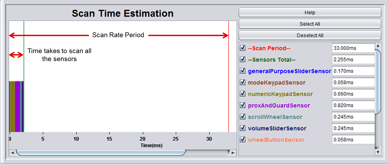 Figure 31. Scan Time Estimation
 3. Touch Debounce
- This parameter was set in the reliability checklist and also affects the response time.
- The time it takes for the system to report a touch signal after the sensor touch is detected can be calculated as shown in Figure 32.
 Figure 32. Response Time Equation
 Step 5b.5: Update Source Code
After real-time tuning and configuration, you can use CapTIvate Design Center to update the source code with the latest tuning parameters. The output directory must be the IDE source code project directory.
 Figure 33. Update Source Code
 Step 5c: Firmware Development
After the basic CapTIvate tuning process, the next step is to complete the firmware development based on specific application requirements.
Step 5c.1: Accessing the Sensor Data
- In general, the CapTIvate software library operates on the principle of refreshing data in objects, rather than returning results directly through a function call.
- It is the responsibility of the application to access the results of a measurement in the appropriate object data structure. A callback function can be registered with any sensor that must be called whenever the sensor data is refreshed.
- The following links are to examples of how to access the sensor data:
Step 5c.2: Customize Communication Code
- Many applications require an interface to communicate the capacitive touch status to a host or driver in the system (for example, another MCU, an LED driver, or a motor driver).
- This interface could be I2C, SPI, UART, or GPIO.
- The CapTIvate library includes a communications module to connect CapTIvate MCUs to external components through the UART or I2C serial interface. Refer to Communications Module for details.
Step 5c.3: Optimize Low Power Consumption
- If the application is battery powered and requires extremely low power consumption to extend the battery life and product shelf life, it is critical to optimize the system power consumption.
- The CapTIvate peripheral on MSP430 MCUs enables user interface designs with extremely low power consumption. Low power consumption is possible because the CapTIvate peripheral includes a processing state machine that performs basic functions while the MCU is in LPM3 without any CPU interaction.
Refer to Ultra Low Power Optimization for details.