SLAU298A November 2009 – May 2021
- Trademarks
- 1ADS8555EVM-PDK Overview
- 2EVM Analog Interface
- 3Digital Interface
- 4Power Supplies
- 5Installing the ADS8555EVM Software
-
6ADS8555EVM Operation
- 6.1 Connecting the Hardware and Running the GUI
- 6.2 Jumper Settings for the ADS8555EVM
- 6.3 Modifying Hardware and Using Software to Evaluate Other Devices in the Family
- 6.4 EVM GUI Global Settings for ADC Control and Registers
- 6.5 Time Domain Display
- 6.6 Frequency Domain Display
- 6.7 Histogram Display
- 7Bill of Materials, Layout, and Schematics
- 8Revision History
6.1 Connecting the Hardware and Running the GUI
- Set the jumpers according to Section 6.2.
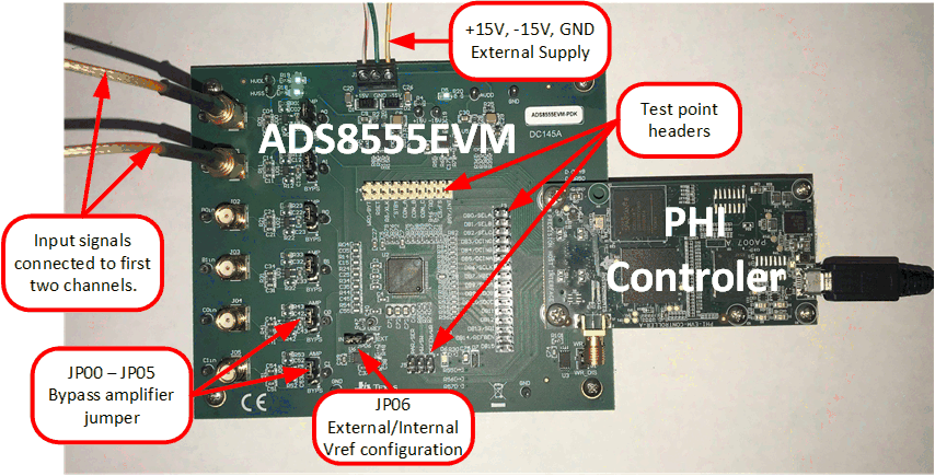
- Physically connect P2 of the PHI to J10 of the ADS8555EVM. Install the screws to assure a robust connection.
- Connect the USB on the PHI to the computer first.
- LED D5 on the PHI lights up, indicating that the PHI is powered up.
- LEDs D1 and D2 on the PHI start blinking to indicate that the PHI is booted up and communicating with the PC; Figure 6-1 shows the resulting LED indicators.
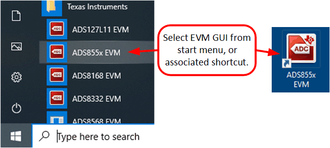
- As shown in Figure 6-2, start the software GUI. Notice that the LEDs blink slowly when the FPGA firmware is loaded on the PHI. This process takes a few seconds, afterwards the AVDD and DVDD power supplies turn on.
- Connect the external ±15-V power supplies and GND to J1. This connection generates the AVDD, HVDD, and HVSS supplies (HVDD = 12 V, HVSS = –12 V, and AVDD = 5 V).
- Connect the signal generator. The default input range is ±10 V (or 10 Vpk). A common input signal applied is a sinusoidal 1-kHz, 9.9-Vpk signal with a 0-V offset. This signal is adjusted just below the full-scale range to avoid clipping.
 Figure 6-1 ADS8555EVM Hardware Setup and LED Indicators
 Figure 6-2 Launch the EVM GUI Software