SLAU298A November 2009 – May 2021
- Trademarks
- 1ADS8555EVM-PDK Overview
- 2EVM Analog Interface
- 3Digital Interface
- 4Power Supplies
- 5Installing the ADS8555EVM Software
-
6ADS8555EVM Operation
- 6.1 Connecting the Hardware and Running the GUI
- 6.2 Jumper Settings for the ADS8555EVM
- 6.3 Modifying Hardware and Using Software to Evaluate Other Devices in the Family
- 6.4 EVM GUI Global Settings for ADC Control and Registers
- 6.5 Time Domain Display
- 6.6 Frequency Domain Display
- 6.7 Histogram Display
- 7Bill of Materials, Layout, and Schematics
- 8Revision History
1.1 ADS8555EVM-PDK Features
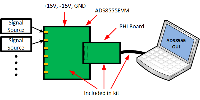
Figure 1-1 shows the proper component connection for the ADS8555EVM. The ADS8555 evaluation module kit includes the following features:
- Hardware and software required for diagnostic testing as well as accurate performance evaluation of the ADS8555 ADC.
- Digital and analog interface power with universal serial bus (USB) power. External power is required for the high-voltage ±15-V supply.
- Easy-to-use evaluation software for the 64-bit Microsoft® Windows®7, Windows® 8, and Windows® 10 operating systems.
- Precision host interface (PHI) controller translates the USB (2.0) or higher to parallel or serial digital communications.
 Figure 1-1 System Connection for
Evaluation