SLLA498 October 2020
5.1 Two-level H-bridge Inverter
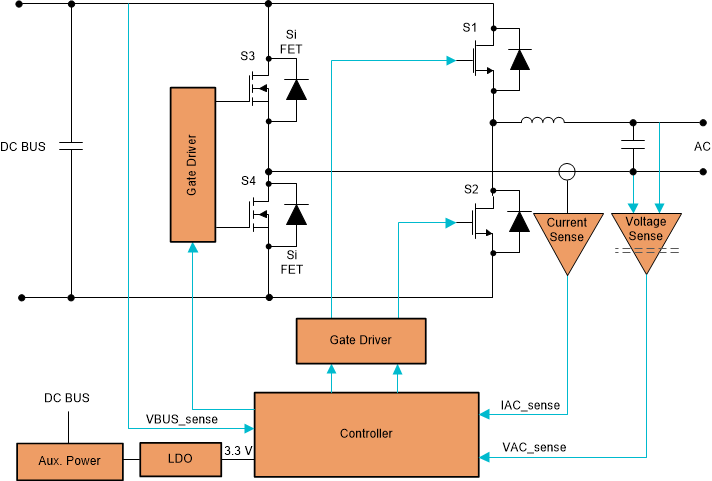
Figure 5-1 shows the two-level H-bridge inverter topology which is a conventional bridge inverter in which one half of the bridge uses fast switching devices S1 and S2, and the other half (S3 and S4) uses slow (100 Hz and 120 Hz) switching devices (unipolar mode). All four devices can be made to switch at high frequency (bipolar mode) to improve waveform shape; but it results in more switching losses.
 Figure 5-1 Two-level H-bridge Inverter.
 The current flows only through two switches at a time. S1/S2 are driven synchronously with complimentary PWM signals and the S3/S4 on the slow line frequency legs can be low RDS(on) Si MOSFETs to further reduce conduction loss. The two level H-bridge is inherently capable of bidirectional operation (in opposite direction, it works as a totem-pole PFC), which is ideal for ESS integrated string inverters. Since switching is only between two levels (either VDC or zero), the harmonic distortion of the generated voltage waveform can be relatively higher. Another disadvantage is that with silicon MOSFETs, the totem-pole arrangement allows operating in only discontinuous-conduction mode (DCM) or critical-conduction mode (CrM) because if continuous-conduction mode (CCM) is allowed, the reverse recovery of the MOSFET body diodes (which is much higher than that of standard fast-recovery diodes) can cause excessive losses. So typically IGBTs are used with only moderately high switching frequencies (below 25 kHz) when CCM operation is required. However, with the advent of silicon carbide (SiC) and gallium nitride (GaN) switching devices with zero-recovery reverse conduction has made it possible to operate in CCM operation even at high switching frequencies.
This topology is demonstrated in the TI reference designs C2000™ Solar DC/AC Single Phase Inverter and Single-Phase Inverter Reference Design with Voltage Source and Grid Connected Modes. Even though a two level H-bridge can give only a single phase output, a full three arm bridge can give three phase output as demonstrated in the TI reference design Three-Phase Inverter Reference Design Using Gate Driver With Built-in Dead Time Insertion. This bidirectional DC/AC topology is an option to consider for the bidirectional DC/AC stage (see Figure 3-1) between the HV DC Bus and the AC Bus in a storage ready solar inverter.