SLPU010 September 2022 JFE2140
4.2 PCB Layout
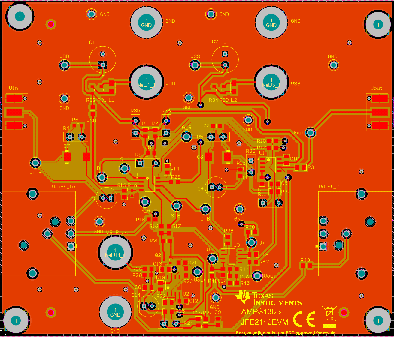 Figure 4-2 JFE2140EVM PCB Layout
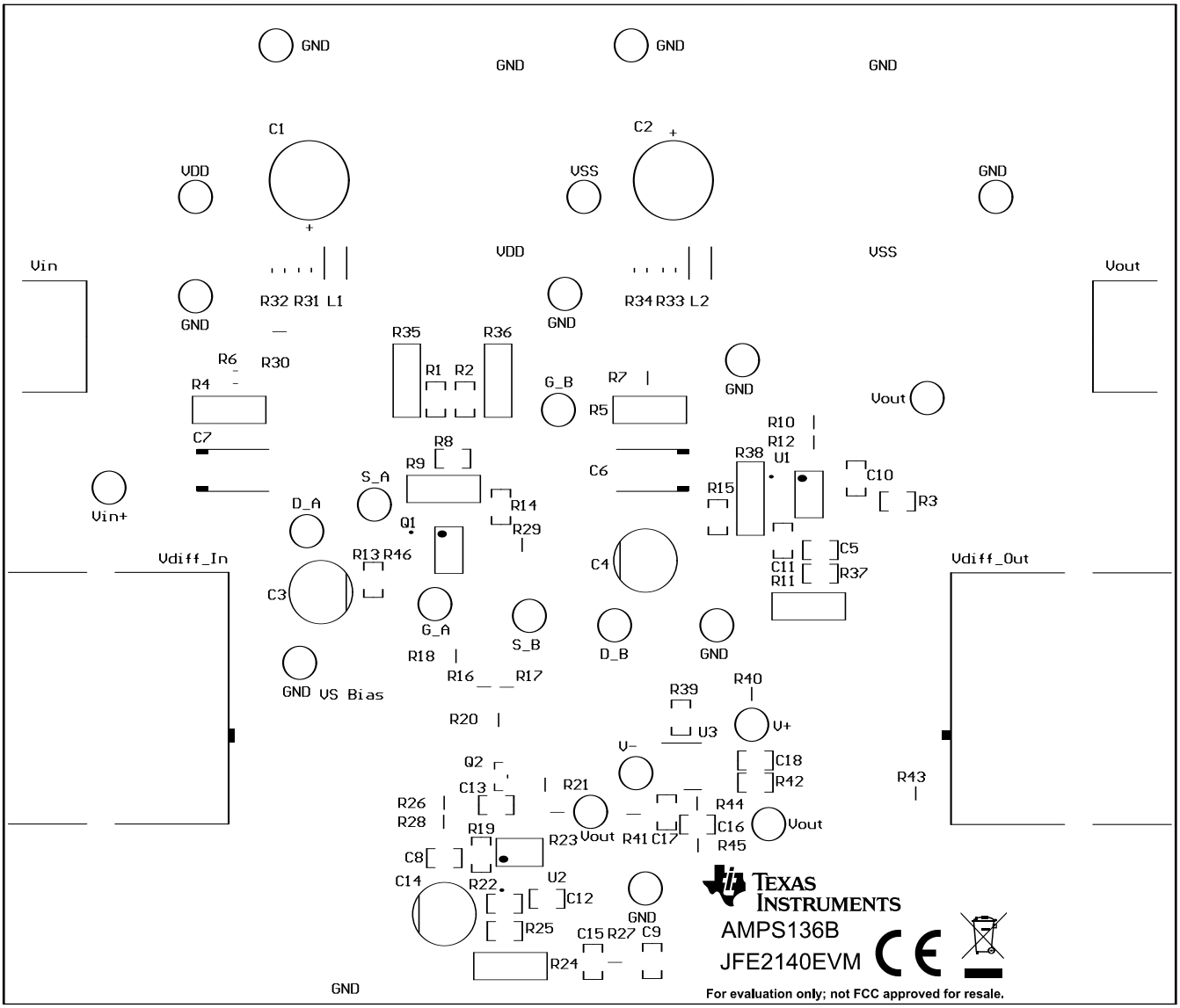 Figure 4-3 JFE2140EVM Top Overlay
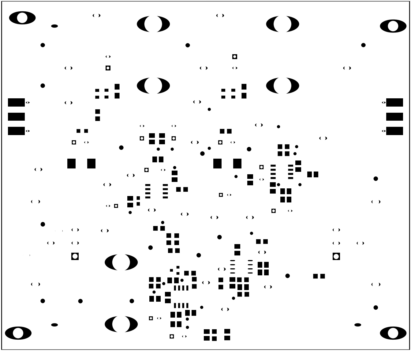 Figure 4-4 JFE2140EVM Top Solder Mask
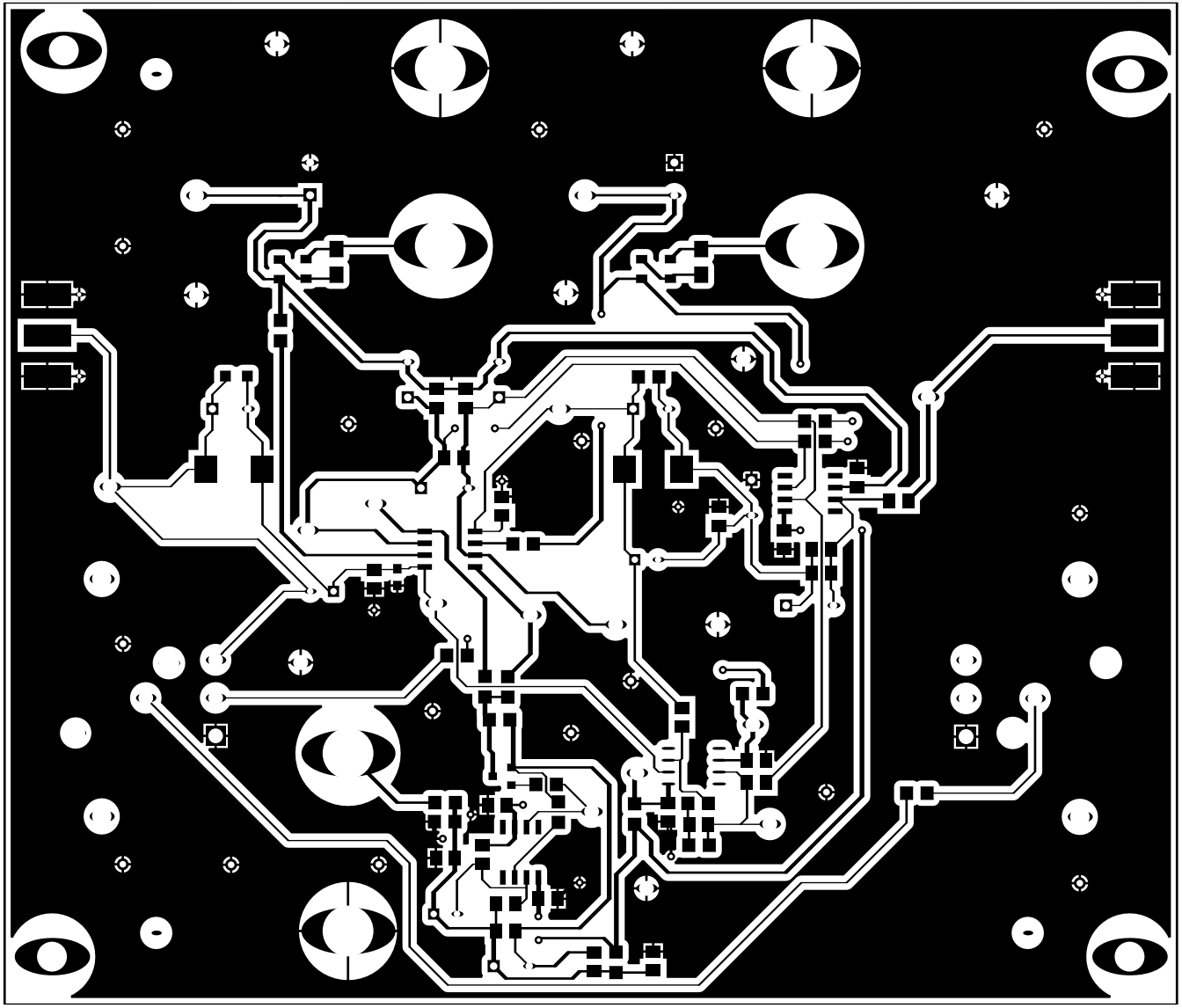 Figure 4-5 JFE2140EVM Top Layer
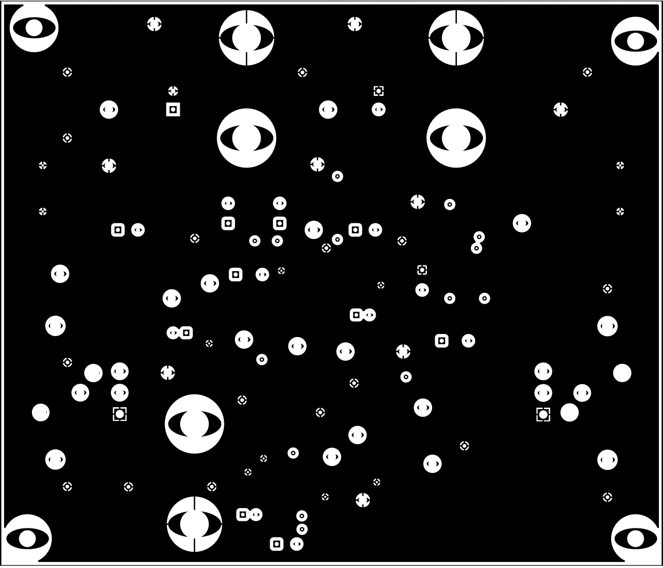 Figure 4-6 JFE2140EVM Signal Layer 1
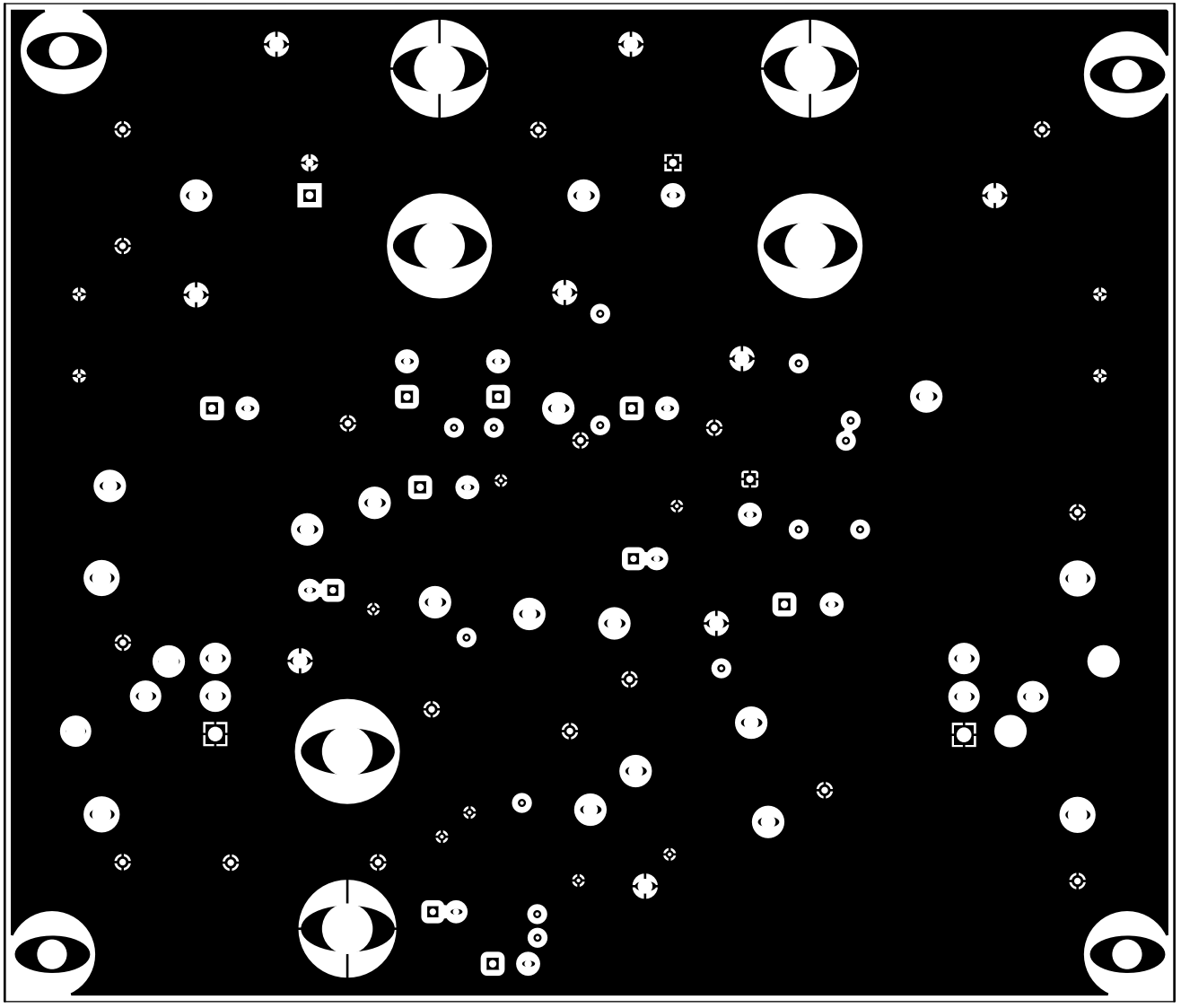 Figure 4-7 JFE2140EVM Signal Layer 2
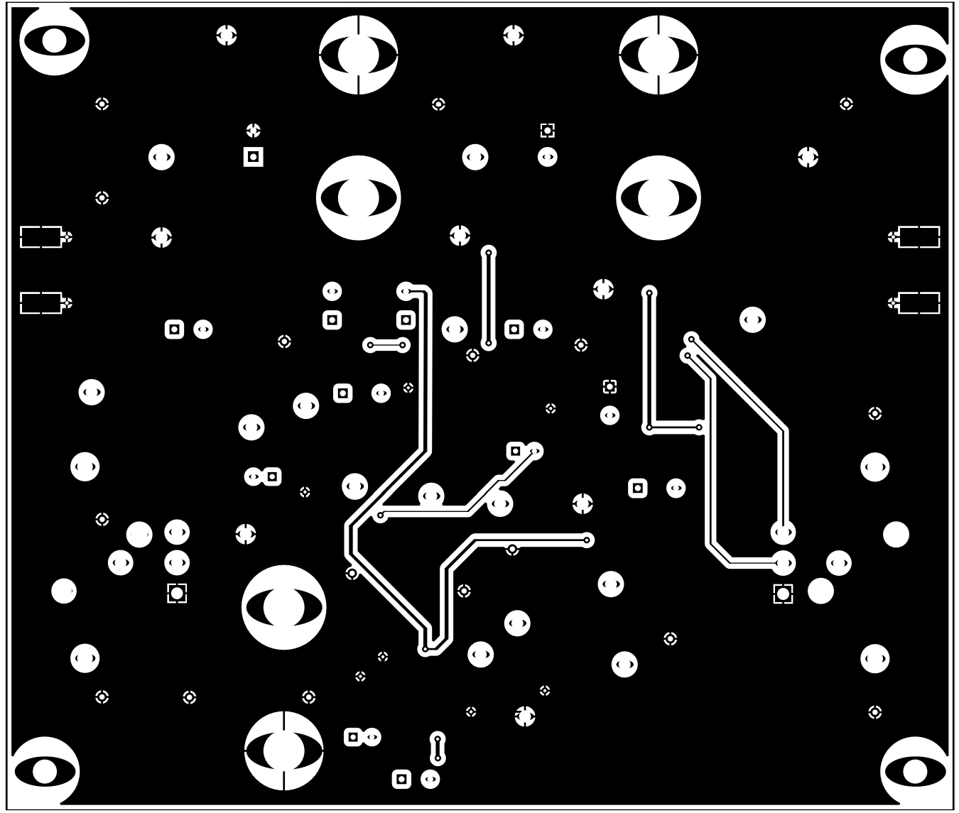 Figure 4-8 JFE2140EVM Bottom Layer
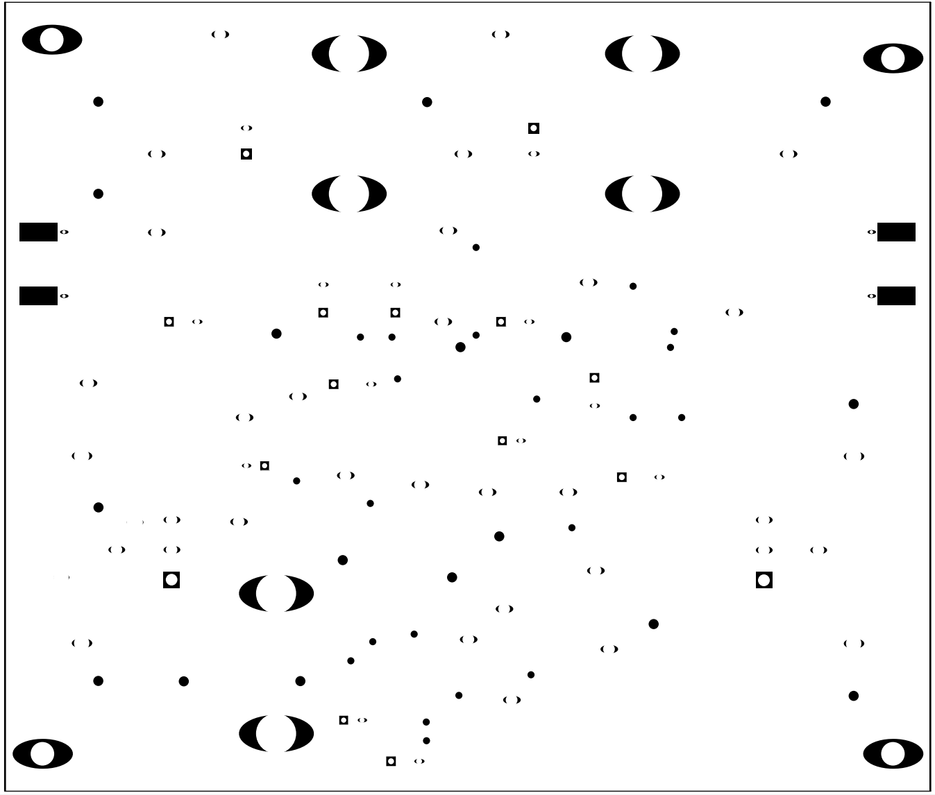 Figure 4-9 JFE2140EVM Bottom Solder Mask
 Figure 4-10 JFE2140EVM Drill Drawing
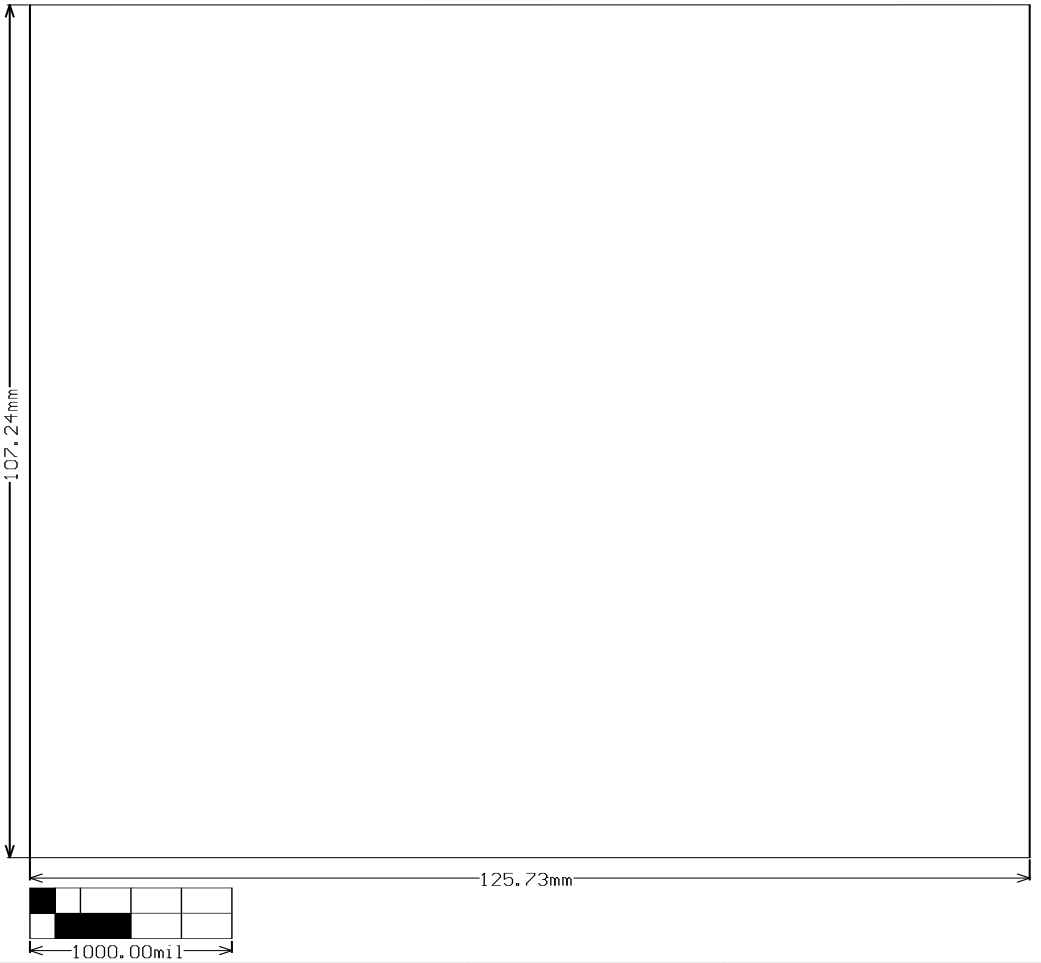 Figure 4-11 JFE2140EVM Board Dimensions