SLUAAH1 December 2021 UCC24624
2.4 Multi SR Controllers with Matrix Transformer Configuration
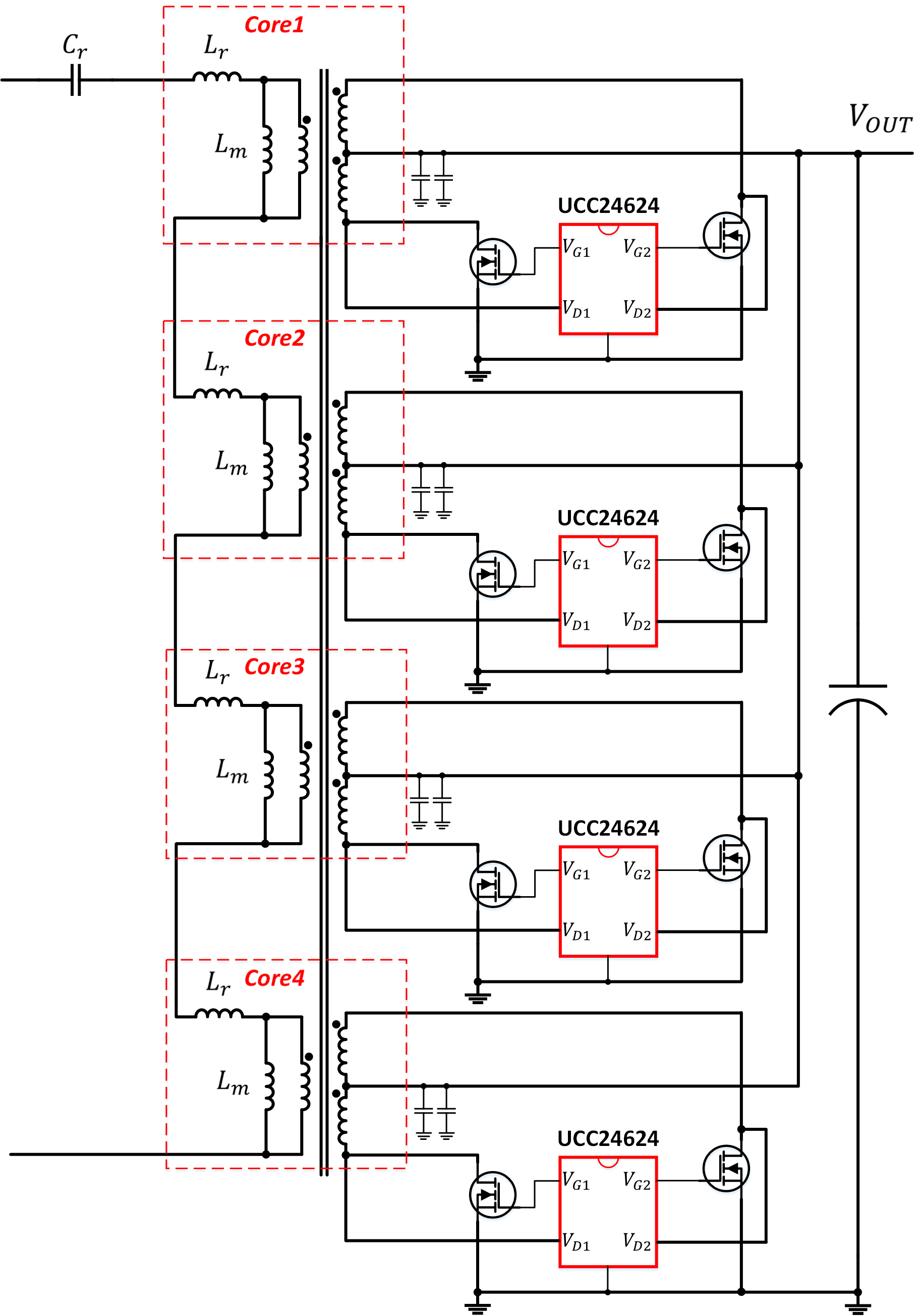
For applications that require low-voltage and high-current outputs, such as OLED TV, server, or telecom, a matrix transformer with multi SR controllers is an attractive solution. The concept of matrix transformer is to use several small transformers to replace the single big transformer, with the primary-side windings in series and the secondary-side windings in parallel. Since the primary-side current for different transformers is the same due to a series connection, the secondary current is balanced.
The benefits of the matrix transformer are that it can share current among secondary windings, reduce leakage inductance and winding resistance, and improve thermal performance by distributing the power loss throughout the transformers.
In Figure 2-4, a single transformer is divided into four transformers.
 Figure 2-4 Multi UCC24624 with Matrix Transformer Application Schematic
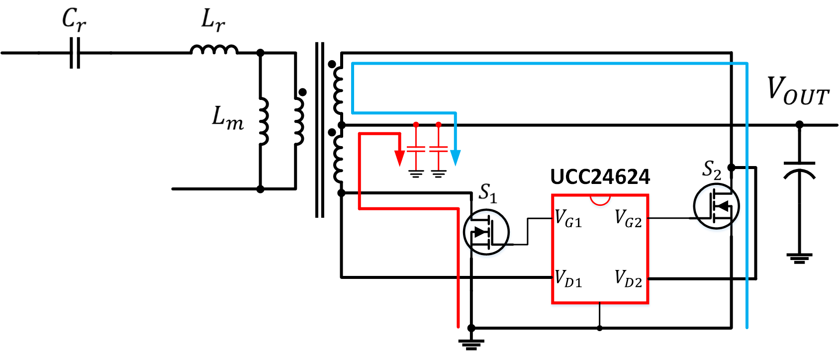
It is recommended to put the ceramic capacitor locally close to center-tap to filter out the high frequency current and improve the efficiency. Since the electrolytic capacitor has large ESL and ESR, the added ceramic capacitors normally can bypass all the high- frequency current.
 Figure 2-5 Recommended AC Coupling Ceramic Capacitors
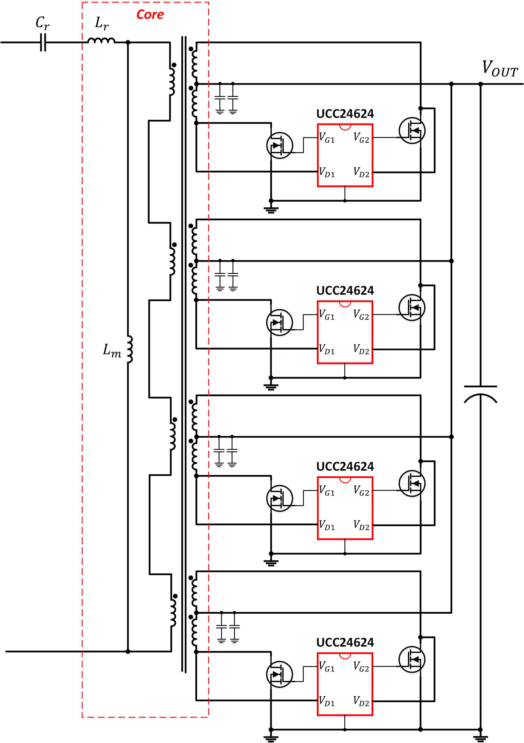
Furthermore, a novel matrix transformer structure can be integrated multiple transformers into a single core as shown in Figure 2-6. This winding structure fully utilizes the available PCB copper and space, further minimizes the core loss. For more detailed winding of the transformer, please refer to reference [6].
 Figure 2-6 Multi UCC24624 with Novel Matrix Transformer Application Schematic