SLVU876A February 2013 – May 2021 TPS65279V
5.3 Hardware Setup
After connecting the power supply to J1, turn on the power supply, and connect JP1 to Vin through a 100-kΩ resistor, connect JP2 to Vin through a 100-kΩ resistor, connect JP7 to GND, connect JP8 to GND, the EVM will regulate the output voltages to the values shown in Table 2-1. Additional input capacitance may be required in order to mitigate the inductive voltage droop that may occur during a load transient event.
The output voltage is changed by sending the digital control signal via a PC running the TPS65279V controller software and USB-TO-GPIO interface box. Change the output voltage with the following steps:
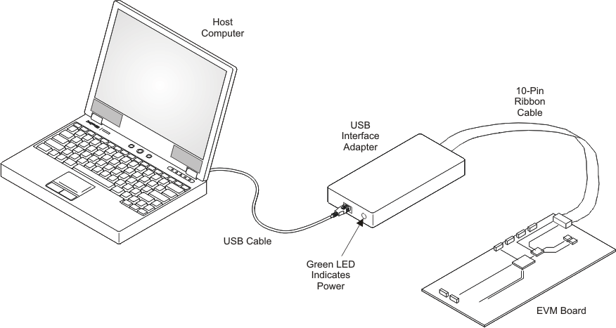
- Connect one end of the USB-TO-GPIO box to the PC using the USB cable and the other end to JP15 of the TPS65279V using the supplied 10-pin ribbon cable as shown in Figure 5-2. The connectors on the ribbon cable are keyed to prevent incorrect installation.
- Connect the power supply on J1, and turn on the power supply.
- Run the software as explained in the next section.
 Figure 5-2 USB Interface Adapter Quick Connection Diagram