SLVUBO3A April 2019 – October 2020 TPS650330-Q1
- Trademarks
- 1BOOSTXL-TPS65033 Components and Environment
- 2BOOSTXL-TPS65033 Board Information
- 3Programming GUI Operation
- 4Recommended Operating Procedure
- 5BOOSTXL-TPS65033 Schematic
- 6BOOSTXL-TPS65033 Board Layers
- 7BOOSTXL-TPS65033 Bill of Materials
- 8Revision History
3.3.3 Registers
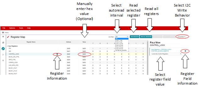
The Registers section provides an overview of the internal register map, and includes basic interfaces for each PMIC register. Figure 3-14 illustrates the register page and the primary interactive regions.
 Figure 3-14 Register Page Interfaces
The register table displays each register name, address, last known value from the PMIC, and corresponding bit values. Selecting a title or bit fields in the table will update the Field View column on the right side of the GUI. The Field View displays the individual fields contained within the associated register address. Within the register page, clicking a blue icon containing a question mark (?) will expand additional descriptions if available. The expanded description views can then be closed by clicking the red (x) icon.
This register page can poll the device periodically using the Auto Read feature in the top right corner, or allow manual read instructions using the Read Register and Read All Registers buttons.
A drop-down menu selection at the top right of the register map indicates how the registers are written as the user interacts with the register page. With Immediate selected, any update to the register page is automatically sent to the PMIC, whereas Deferred will wait for the Write Register or Write All Registers instructions before communicating with the device. After each write, the register page will automatically read the affected register address to confirm the latest value in the device.