SLVUC00 September 2020 – MONTH
6.2 Rise Time Test Setup
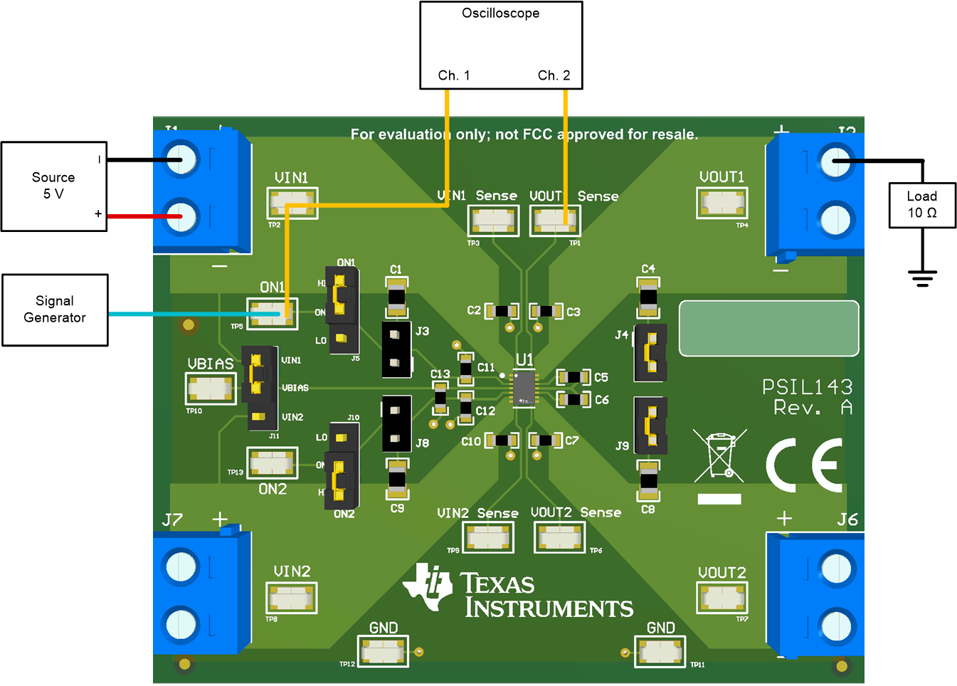
Figure 6-2 shows the test setup for measuring the rise time of the TPS22976A. Apply a square wave to the ON pin of the switch using a function generator and apply a voltage to the VIN terminal using a power supply. Observe the waveform at VOUT Sense (TP1/TP6) with an oscilloscope to measure the slew rate and rise time of the switch with a given input voltage. To vary the output voltage rise time, change the default 1000-pF CT capacitors (C5/C6). For more information on the rise time variance with CT capacitor value, refer to the TPS22976 5.7-V, 6-A, 14-mΩ On-Resistance Dual-Channel Load Switch data sheet.
 Figure 6-2 Rise Time Test Setup