SLVUC48 August 2021 TPSM560R6
3 Test Results
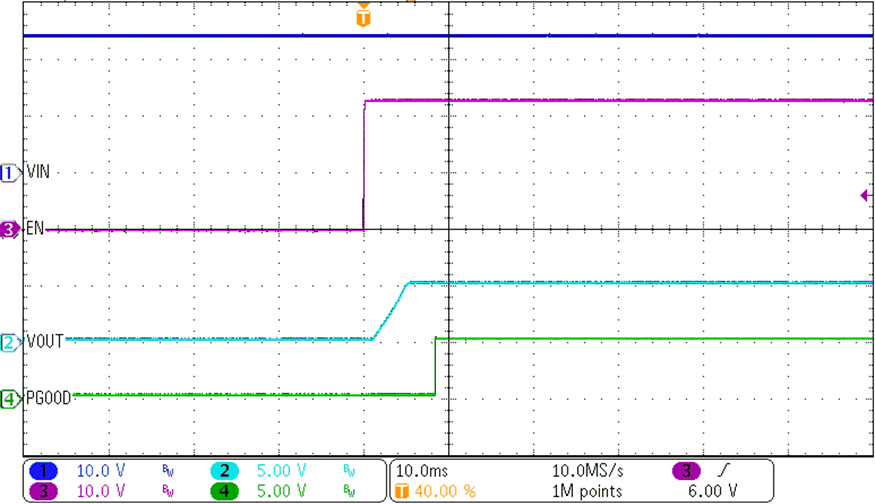
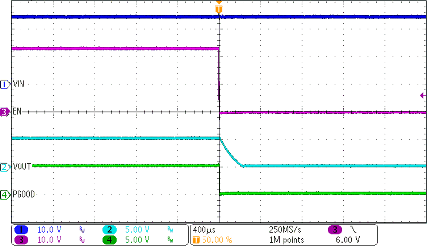
Figure 3-1 through Figure 3-4 demonstrate the performance of the TPSM560R6EVM under the following condition of a 24-V input voltage, 5-V output voltage and 600-mA load.
 Figure 3-1 ENABLE Start-Up Waveform
Figure 3-3 Output Voltage Ripple
 Figure 3-2 ENABLE Shutdown Waveform
Figure 3-4 Transient Performance