SNIA044 November 2021 TMP61 , TMP61-Q1 , TMP63 , TMP63-Q1 , TMP64 , TMP64-Q1
3.3 Differential Temperature Measurement Design Guidelines
The technique of differential temperature measurements may seem simple, but there are several factors that to consider to accurately monitor the critical component.
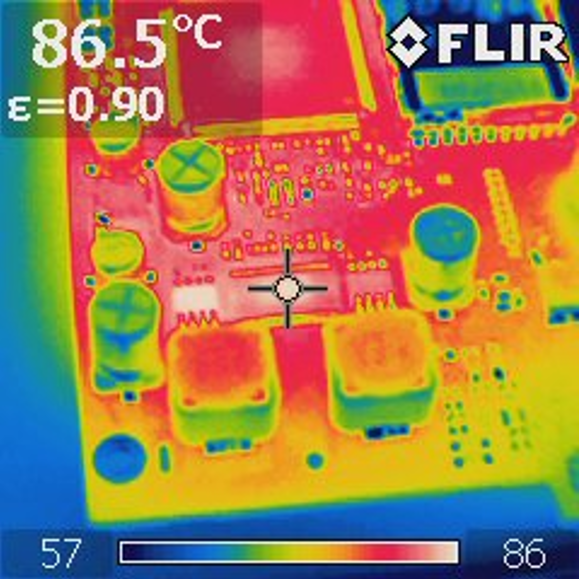
Most importantly, use an infrared thermal camera to measure the hot spot on the IC to represent the die temperature, then calculate the temperature delta ratio based on the die temperature and the two external temperature measurements. The thermal camera is effective because of its ability to detect the emitted thermal radiation (ETR) that is reflected off the top of the encapsulated material above the IC die area, as shown in Figure 3-7. Much like the image of a person or light is seen in the reflection on a window pane; the ETR is visible on the top of the IC package and can be measured by the thermal camera. This is similar to how a thermal camera can measure through walls. A thermal camera cannot really identify objects through walls, but, if it is sensitive enough, it can detect the ETR of a human body on the walls. The thermal measurement through the IC package can be as accurate as ±0.2°C. The losses are minimal at this distance, but the accuracy is diminished by the emissions that spread in all directions, much like a light would shine in an outward spreading pattern.
 Figure 3-7 Thermal Capture of Emitted Thermal Radiation Above and IC
The board must also have a designated thermal layout. There are several options to consider when designing the thermal layout of a PCB using the differential temperature measurement technique. Option 1 is to use the ground plane to achieve good thermal flow across the PCB and use vias to the ground plane to take the temperature measurements. Option 2 involves using the thermal flow across a heatsink and two temperature sensors at different locations along the heatsink to take the differential measurements. Option 3 is to use a dedicated thermal trace. Options 1 and 2 tend to provide the best low-impedance heat path, but option 3 can be used to create a thermal path if one does not exist. If a dedicated thermal trace is needed, the concept of squares can be used to estimate the ratio of the thermal resistances, which should later be verified using a thermal camera.
The concept of squares is based on thermal resistance and heat-conduction physics but is applied using Ohm’s law. The thermal trace is made up of squares, where the width of the trace defines the length of one thermal square. In Figure 3-8, the distance between thermistors R1 and R2 is two squares of thermal trace. The distance between the source and R1 is five squares.
In this example, the estimated ratio of the thermal resistances based on the concept of squares is 5 / 2 or 2.5. This concept can help simplify the technique of differential measurements, but using a thermal camera to calculate the ratio of the die temperature and the two external temperature measurements provides the best results because there is a high potential for error if all factors are not considered.
Use the following additional guidelines to maintain the accuracy of the differential thermal calculation:
Extend the length of the thermal trace beyond the two differential measurement points to help prevent thermal saturation of the trace
Keep the thermal trace as far away from outside heat sources as possible
Ensure the thermal trace has consistent width and consistent spacing from the ground plane
Keep the thermal trace as straight as possible
If a via is used in one thermal location, use vias for the other two as well
Routing the thermal trace on an internal layer results in less interference from outside air movement or ambient temperatures than a thermal trace routed on an external layer