SNVU751 October 2020 LP875761-Q1
3.2 Power Supply Setup
To power up the EVM, one power supply is needed. For full-load testing of the LP875761Q1EVM, a DC-power supply capable of at least 10 A and 5 V is required. 5 A is suggested as a practical minimum for partial load. The power supply is connected to the EVM using connector J4. The power supply and cabling must present low impedance to the UUT; the length of power supply cables must be minimized. Remote sense, using connector J8, can be used to compensate for voltage drop in the cabling.
With the power supply disconnected from the UUT, set the supply to 3.3 V or 5.0 V DC and the current limit to 5 A minimum. Set the power supply output OFF. Connect the power supply's positive terminal (+) to VIN and negative terminal (–) to GND on UUT (J4 power-in terminal block). Check that jumpers on the boards are set as shown in Figure 2-1 (factory default jumper configuration).
Set power supply output ON, and then continue with the following steps. Note that following steps are only an example. Register values, enable control, mode and multiphase status may differ depending on the LP875761Q1EVM configuration.
- On Evaluation software GUI, click on Assert NRST (see Figure 3-6).
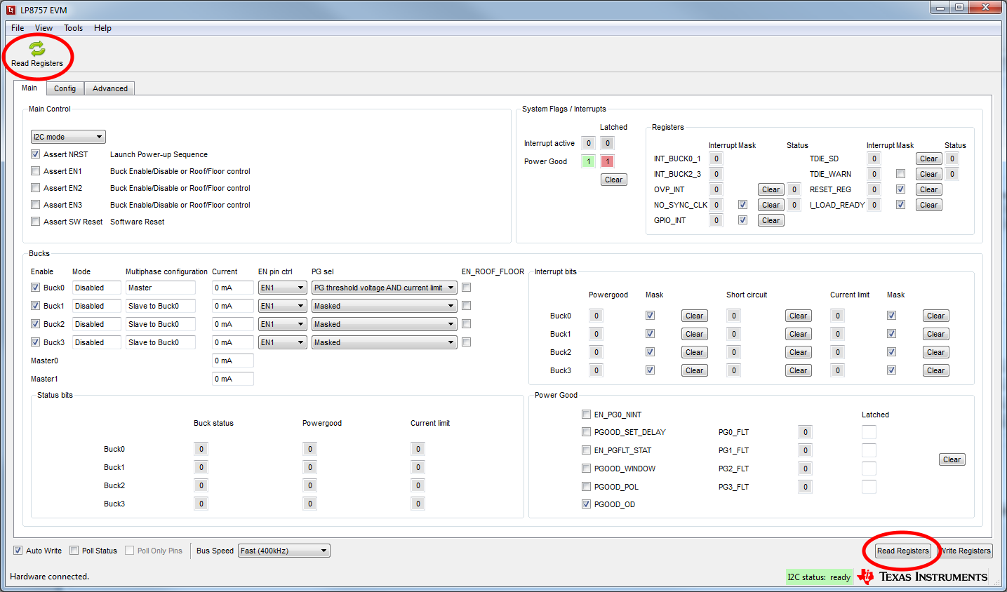
- Click on either of the two Read Registers buttons. You should see ready message on green background next to the Read Registers button (see Figure 3-7).
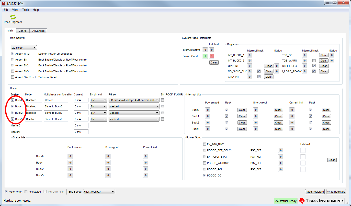
- Check that Buck0 is enabled, checkbox is ticked (see Figure 3-8).
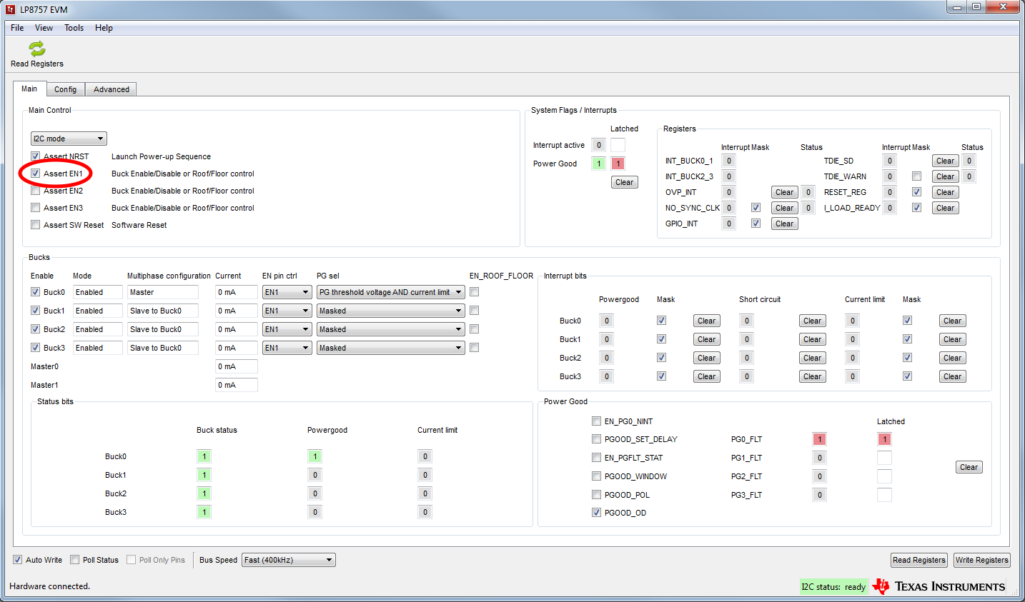
- Click on Assert EN1 (see Figure 3-9).
- Click on either of the two Read Registers buttons.
- In this example case the GUI indicates Disabled under Mode until EN1 is asserted. After EN1 is asserted Mode is changed to Enabled. In case BUCKx is enabled or disabled with bit instead of ENx pin, the Mode can be checked by reading registers. GUI indicates also Master under Multiphase status of Buck 0. Mode of other bucks are Disabled and Multiphase status is Slave to Buck0. The EVM is now ready for testing with default register settings loaded.
 Figure 3-6 Assert nRST
 Figure 3-7 Read Registers Buttons
 Figure 3-8 BUCK0 Enabled
 Figure 3-9 Assert EN1