SPNA239 September 2019 RM46L440 , RM46L450 , RM46L830 , RM46L840 , RM46L850 , RM46L852 , RM48L530 , RM48L540 , RM48L730 , RM48L740 , RM48L940 , RM48L950 , RM48L952 , RM57L843 , TMS570LC4357 , TMS570LC4357-EP , TMS570LC4357-SEP , TMS570LS0232 , TMS570LS0332 , TMS570LS0432 , TMS570LS10106 , TMS570LS1114 , TMS570LS1115 , TMS570LS1224 , TMS570LS1225 , TMS570LS1227 , TMS570LS20206 , TMS570LS20206-EP , TMS570LS20216 , TMS570LS20216-EP , TMS570LS2124 , TMS570LS2125 , TMS570LS2134 , TMS570LS2135 , TMS570LS3134 , TMS570LS3135 , TMS570LS3137 , TMS570LS3137-EP
-
HALCoGen Ethernet Driver With lwIP Integration Demo and Active Web Server Demo
- Trademarks
- 1 Introduction
- 2 Supported Features
- 3 Get the Software
- 4 Configuring EMAC and MDIO Using HALCoGen GUI for the lwIP Demo
- 5 Additional Changes for Active Web Server Demo
- 6 Programming Sequence Using HALCoGen Generated Drivers
- 7 Design of lwIP Integration
- 8 Release Folder Structure
- 9 Run the Test
9.2 Building and Executing the lwIP Demo
- Import the project into CCS from <install_folder>/<device>/Build_xx folder, based on the board.
- Build the project. Default target configuration is supplied with this software.
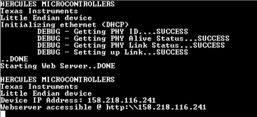
- Download and execute the binary (disconnect the device from debugger and reset). Figure 5 shows a screen capture of the console output.
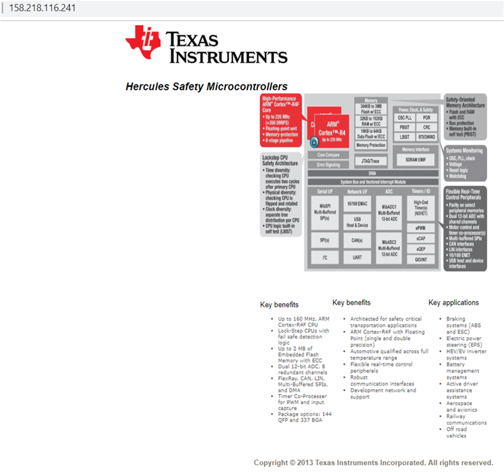
- The web server is accessible at the IP address displayed in the console.
 Figure 5. Demo UART Console Output
  Figure 6. Web Server From lwIP Demo