SPRACM7 December 2020 F29H850TU , F29H859TU-Q1 , TMS320F280021 , TMS320F280021-Q1 , TMS320F280023 , TMS320F280023-Q1 , TMS320F280023C , TMS320F280025 , TMS320F280025-Q1 , TMS320F280025C , TMS320F280025C-Q1 , TMS320F280040-Q1 , TMS320F280040C-Q1 , TMS320F280041 , TMS320F280041-Q1 , TMS320F280041C , TMS320F280041C-Q1 , TMS320F280045 , TMS320F280048-Q1 , TMS320F280048C-Q1 , TMS320F280049 , TMS320F280049-Q1 , TMS320F280049C , TMS320F280049C-Q1 , TMS320F28384D , TMS320F28384D-Q1 , TMS320F28384S , TMS320F28384S-Q1 , TMS320F28386D , TMS320F28386D-Q1 , TMS320F28386S , TMS320F28386S-Q1 , TMS320F28388D , TMS320F28388S , TMS320F28P550SJ , TMS320F28P559SJ-Q1 , TMS320F28P650DH , TMS320F28P650DK , TMS320F28P650SH , TMS320F28P650SK , TMS320F28P659DH-Q1 , TMS320F28P659DK-Q1 , TMS320F28P659SH-Q1
2.4 Run-Time System Monitoring, Diagnosis and Response Generation in Real-Time Systems
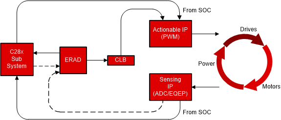
Thus far it has been shown that the ERAD module is acting as a monitoring agent. However, when used in conjunction with the Configurable Logic Block (CLB), it is possible to create a real-time response to various ERAD generated events. In this scenario, the ERAD defines and detects various system scenarios and the CLB drives a corrective action utilizing its connections to key peripherals such as the ePWM or direct control over a GPIO (like setting an ERROR pin).
Figure 2-3 shows a conceptual power stage control inside the C2000 MCU and how the ERAD plus CLB could be inserted in the control loop for non-intrusive monitoring as well as support with quick response to anomalies. There is potential for an out of bound condition to cause erroneous outputs to be driven out to the power stage of the system. The result of which could be a range of system effects anywhere from an inefficient system to potential damage to the power electronics.
Even if some of these anomalies cause critical interrupts to be generated, it will take a few micro-seconds for the CPU software to execute the interrupt service routine, diagnose the issue in software and generate a corrective remedial response.
 Figure 2-3 Run-Time Monitoring and
Response
Figure 2-3 Run-Time Monitoring and
ResponseFurthermore, the CLB can do a second level of analysis on the generated events to create a spatial relationship profile. The temporal relationship between a specific system interrupt and time taken for the Interrupt code to be executed can be constrained with a fixed threshold and report back using another interrupt if the system load does not allow this.
For example, consider that PWM module sends an ADC conversion request via EPWMxSOCA/B and the ADC hardware senses the request and initiates a conversion followed by an interrupt to indicate the completion. This in general initiates a control loop execution based on the sensed ADC value, which needs to be executed within a prescribed time decided by the system integrator. One of the variable factors here is the interrupt being taken on time, once the ADC generates an interrupt request. There is no guarantee that the CPU will start this ISR after ADC sends the interrupt request, as it could be executing another higher priority task. ERAD/CLB combo can help define a threshold time by when the interrupt execution should have started from PWM issuing EPWMxSOC, if not create a PWM Trip.
To design a system to address the above problem using ERAD and CLB, consider that CLB gets two events:
- EPWMxSOC input comes to CLB directly, which also signals ADC to start conversion (Counter start)
- ERAD is used to create an event when the ADC ISR start address is executed (Counter stop)
Using both these events to start and stop a counter, a threshold value can be set to create a trigger event if the later/stop event does not come on time. This event can be used to generate a PWM Trip if the ADC interrupt is not taken within the prescribed time.
In summary, ERAD plus the CLB allows for critical on-chip monitoring and graceful recovery options. In most existing control systems this level of monitoring is either not present, requires a non-sustainable CPU overhead, or requires an expensive external solution. For details on its capabilities and programming, see the CLB architecture and documentation located in the device-specific TRM.
For additional details on hardware and software source that can help to jump start using ERAD, see Section 4.