SSZT099 january 2022 HDC3020-Q1 , TMP102-Q1 , TMP112-Q1 , TMP114 , TMP235-Q1 , TMP61-Q1
If your first car was anything like mine, it probably lacked sensor modules such as cameras, radar and lidar, which make the safety features of modern advanced driver assistance systems (ADAS) like blind-spot detection, park assistance and collision avoidance possible. Because the data collected by these sensor modules directly correlates with passenger safety, it’s important that they work properly over time. Unfortunately, one of the most common causes of damage is prolonged overtemperature operation or exposure to moisture.
Accurate temperature sensors in cameras, radar and lidar can help increase their longevity, safety and reliability. Let’s first take a look at the effects of temperature in automotive camera modules.
Camera
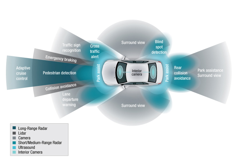
Figure 1 illustrates that there can be as many as six cameras per vehicle. These cameras require a high dynamic range and fast response time with great low-light sensitivity. To meet these requirements, designers must protect the image sensor from prolonged operation in high temperatures.
 Figure 1 Overview of ADAS Sensors in Modern Cars
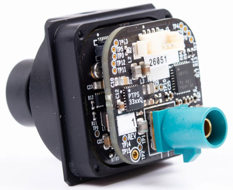
Seen in Figure 2, automotive cameras are often small (1.4 in3) enclosed cubes without active cooling, creating the perfect environment for heat to be trapped and temperatures to rise quickly. Image sensors are typically rated for operation from –40°C to 125°C (junction) and –40°C to 105°C (ambient). If the upper or lower limits of those ranges are reached, the electronics control unit (ECU) will have to reduce power going to the image sensor or completely shut it down until the temperature returns to normal operating conditions. Therefore, it’s important to accurately know the camera’s temperature.
 Figure 2 Small Automotive Camera
Module
Figure 2 Small Automotive Camera
ModuleImage sensors often feature an embedded temperature sensor, which can be inaccurate by ±6°C. This large error means that the ECU might limit the camera’s use by shutting down too early or too late. These miscalculations can cause permanent damage to the image sensor, temporarily limiting ADAS features until it receives maintenance.
The solution is to add a stand-alone temperature sensor which provides accurate temperature measurements within ±1°C. The application note, "Improving System Reliability in Automotive and Industrial Cameras with Accurate Temperature Sensing," can help when selecting a temperature sensor for specific camera topologies
Radar
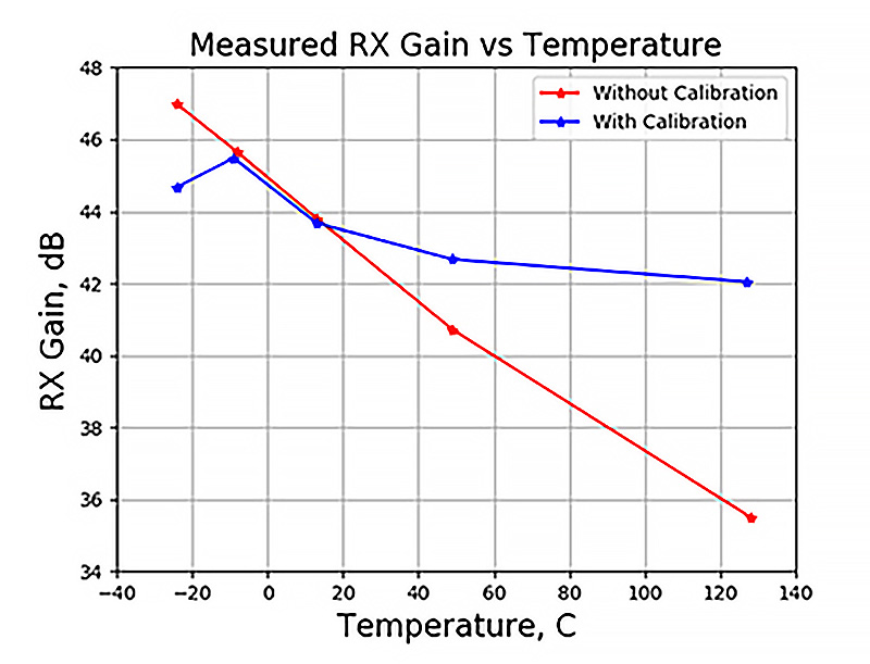
A millimeter-wave (mmWave) sensor’s receiver (RX) sensitivity, gain, input noise and even output transmitter (TX) power can all vary with temperature. In Figure 3, the host processor attempts to mitigate the effect of temperature changes by adjusting circuit configurations periodically during run time to maintain RX gain and TX power close to the configured settings.

 Figure 3 RX Gain (a) and TX Power (b)
over Temperature
Figure 3 RX Gain (a) and TX Power (b)
over TemperatureThe need for highly accurate temperature measurements comes from the delicate balance of maximizing radar performance and preventing thermal damage at high temperatures. To achieve this balance, radar sensors must be pushed to their temperature limits while reliably shutting down as close as possible to them. Accomplishing this may be difficult because:
- OEMs are beginning to require higher ambient temperatures.
- To lower costs, manufacturers are moving towards plastic module enclosures instead of metal. Metal is a better thermal conductor, often used as a heat sink to disperse heat from inside the module.
- Radar chips have high power consumption which leads to self-heating.
- Embedded temperature sensors on radar chips can be up to ±7°C inaccurate which limits the radar chip’s performance. Due to this error, you must be conservative and shut down ±7°C before the operating limit to prevent damage.
Nowadays, designers are targeting ±1°C temperature accuracy for the internal die temperature of radar chips. To achieve this, you could use two stand-alone temperature sensors to conduct a differential temperature measurement, or use an ultra-thin temperature sensor like the TMP114 underneath the radar chip. To learn more about implementing differential temperature measurements, read the application note, "Component Temperature Monitoring Using Differential Temperature Measurements."
For more details on under-component temperature monitoring, read the application note, "Under-Component Monitoring with Ultra-Small Temperature Sensors."
Lidar
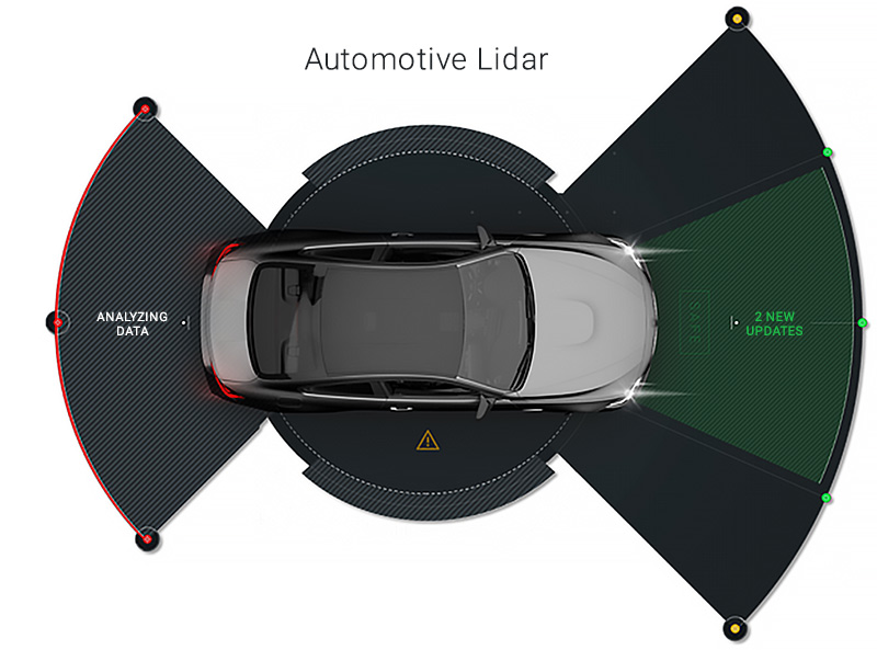
Seen in Figure 4, lidar sensors can capture short, medium and long-range data, providing an in-depth point cloud, serving as a critical component for the safety of ADAS features. Lidar contains laser arrays, time-of-flight (ToF) sensors and a controller which all need to have temperature compensation to maintain their performance. Changes in temperature can affect lidar distance measurements, and at above 70°C the performance of the laser array may decrease. The ToF sensor has high power consumption leading to self-heating, and around 105°C the controller often needs to lower its clock frequency or shut down completely to prevent thermal runaway.
 Figure 4 Automotive Lidar Range
An important design consideration for lidar systems is your targeted automotive safety integrity level (ASIL). The application note, "Meeting ASIL Requirements for LIDAR Systems Using Remote Temperature Sensors," provides a few ideas for quickly implementing redundant and diverse temperature sensors
Both lidar and camera modules have lenses which can crack, potentially leading to moisture damaging the optics inside. An automotive-grade humidity sensor like the HDC3020-Q1 measures relative humidity and temperature. It can detect moisture (which may indicate a leak) and calculate when the dewpoint is crossed (which would lead to condensation on the lens) allowing the system to notify the user to take corrective action.
Choosing a Temperature Sensor
When evaluating your next temperature sensor, consider its maximum accuracy, whether or not you want an alert, or other features, and your communication channels. For example, if there aren’t any ADC channels available, as typically seen in surround view and low-end driver-monitoring cameras, then you could connect a digital temperature sensor to the FPD-Link serializer’s I2C or SPI channels. If you simply want a threshold alert with hysteresis, you could use a temperature switch connected to a general-purpose input/output. When you do have an ADC channel available, analog temperature sensors have an output voltage proportional to temperature without being influenced by external component tolerances like a discrete thermistor solution is. In case you do want a thermistor, silicon-based linear thermistors solve the accuracy and reliability issues that negative temperature coefficient (NTC) thermistors have been known for, while maintaining the same low cost and footprint.
Conclusion
Requirements for accurate diagnostics are very similar among highly sensitive optical and radio-frequency ADAS modules for maximum performance over time. This leads to the adoption of accurate external temperature sensors, a necessary building block of ADAS modules that are rapidly becoming safety-critical systems of the future.