SSZT457 june 2019 ADS1292R , AFE4403 , AFE4420 , AFE4900 , ISOW7821 , TMP117 , TRS3232
Continuous measurement of patient vital signs like heart rate, respiration rate and blood oxygen saturation (SpO2) is crucial for effective care, and the ability to measure those simultaneously makes multiparameter patient monitors increasingly important.
Electronic patient monitors use noninvasive sensors attached to patients to collect and display physiological data. For multiparameter patient monitors, one of the major challenges is achieving a compact size and low power consumption while retaining high performance.
Today, patients that are confined to hospital beds are attached to bulky and expensive multiparameter patient monitors with wires and are not mobile, preventing widespread usage in mobile nursing and home healthcare environments. There is a need for compact multiparameter patient monitors that can be wirelessly attached to a patient and transmit data either wired or wirelessly to display on a mobile phone, tablet or computer.
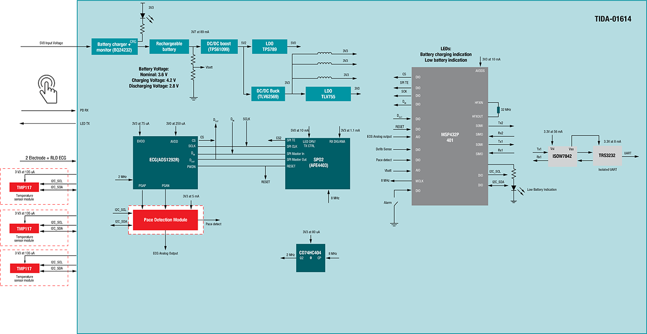
TI’s “Multiparameter front end reference design for vital signs patient monitor” is a compact, low-cost, low-power reference design that incorporates the necessary front-end components to collect key vital signs.
The design captures parameters like electrocardiogram (ECG), SpO2, heart rate and respiration using the AFE4403 and the ADS1292R biosensing front-end integrated circuits. The design interfaces to the Software-configurable cardiac pacemaker detection module reference design to enable pace-pulse detection and connects to three 0.1 Celsius accurate temperature sensors (TMP117) to measure skin temperature. To measure ECG, the design uses standard wet ECG electrodes, and it also uses a transmissive type finger clip sensor to measure SpO2. The captured raw data is available for transfer to a back end/processor or a PC over an isolated Universal Asynchronous Receiver Transmitter (UART) interface at 460.8 Kbps using an onboard MSP432P401 microcontroller. A standard USB port or a lithium-ion battery charged from the USB powers the design.
Figure 1 shows the reference design block diagram.
 Figure 1 Multiparameter Front-end
Subsystem for Vital Sign Patient Monitoring Reference Design
Figure 1 Multiparameter Front-end
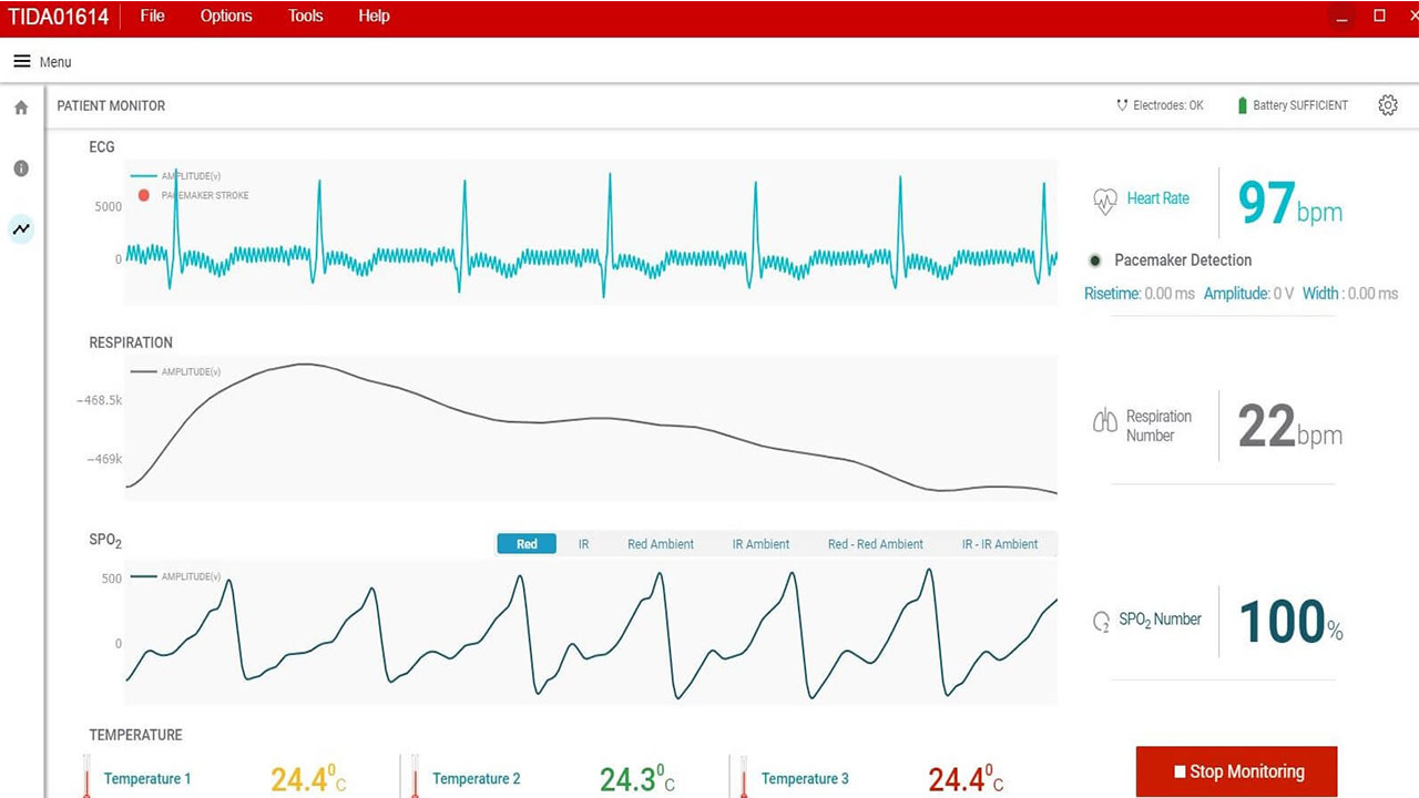
Subsystem for Vital Sign Patient Monitoring Reference DesignA graphical user interface (GUI) displays the captured waveform for a 5-second moving interval while basic filtering cleans up noise such as common-mode interference from power, lights, etc. Figure 2 displays ECG results, respiration and SpO2, along with heart rate in beats per minute, respiration number (breaths per minute), SpO2 percentage and temperature values on a PC.
 Figure 2 GUI Displaying ECG, PPG,
Respiration, Heart Rate and Skin Temperature
Figure 2 GUI Displaying ECG, PPG,
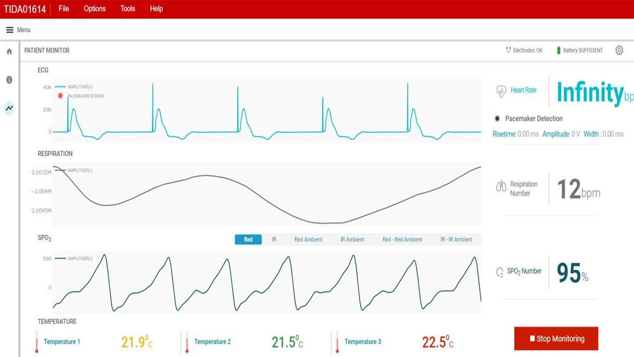
Respiration, Heart Rate and Skin TemperatureFigure 3 shows a measured ECG, photoplethysmography (PPG), pacemaker, heart rate and temperature sensor data on a computer. When a pace pulse is detected, a pace marker shows the presence of pace pulse as indicated by the top line in Figure 3.
 Figure 3 GUI Displaying ECG, PPG,
Pacemaker, Heart Rate and Skin Temperature
Figure 3 GUI Displaying ECG, PPG,
Pacemaker, Heart Rate and Skin TemperatureConclusion
Additional Resources
- Check out these blog posts:
- Download the Analog Design Journal article, "Improving battery life in wearable patient monitors and medical patches."
- Learn more about ultra-low power wired & wireless connectivity solutions across the SimpleLink MCU Platform: www.ti.com/simplelink.