TIDUES6 August 2020 – MONTH
- Description
- Resources
- Features
- Applications
- 5
- 1System Description
- 2System Overview
- 3Hardware, Software, Testing Requirements, and Test Results
- 4Design Files
- 5Software Files
- 6Related Documentation
- 7Terminology
2.4.1 Mirror XY and LED Driver
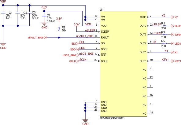
The mirror X&Y angle adjust motors and the LEDs are driven by the DRV8906-Q1. The DRV8906-Q1 has a total of 6 half-bridges. Three of the 6 half-bridges drive the three LEDs and the rest of the half-bridges drive the two brushed DC motors used for X&Y angle adjust.
Figure 2-7 shows the DRV8906-Q1 configuration schematic. To save one half-bridge, the two brushed DC motors are connected in a sequential configuration. In this configuration, the two motors share one half-bridge since the two motors will never be driven simultaneously.
The decoupling capacitors (C1, C2, C3, C4) values are selected based on the recommended values on the data sheet. The nFAULT pin is open drain so a 10-kΩ pullup resistor pulls nFAULT to VDD. Each of the three LEDs have a 200-Ω resistor in series to limit the current.
 Figure 2-7 DRV8906-Q1 Configuration Schematic